Welcome!
By registering with us, you'll be able to discuss, share and message with other members of our community.
SignUp Now!You are using an out of date browser. It may not display this or other websites correctly.
You should upgrade or use an alternative browser.
You should upgrade or use an alternative browser.
cib24's 1999 Mazda RX-7 Type RS
- Thread starter cib24
- Start date
Latest posts
-

-
 I broke it quickly...And repeatedly...Chaste White Rebuild
- Latest: RandomVillager
-
-

- Joined
- Jan 12, 2018
- Messages
- 1,415
February 2016
I promised photos and I have a couple to share of some of the obvious work that was completed. The car wasn't that clean as it had been driven and worked on for the last month but I will take photos of everything cleaned up and washed when the weather is better.
Brake Rotors, Calipers and Pads
Rotors
http://www.dixcel.co.jp/en/rotor/rotor_fcr.html
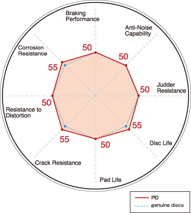
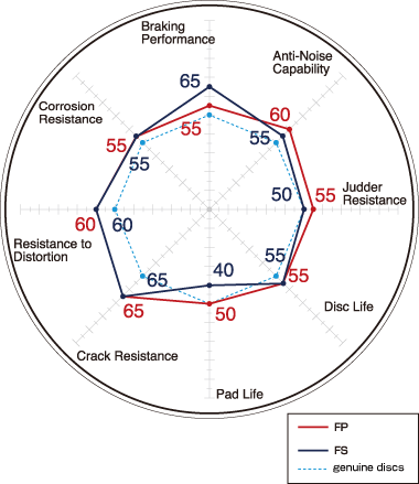
The new brake discs by Dixcel are the same size as the RS rotors that came off the car. The FP are the high performance model from Dixcel (at least for the FD) and have a 20% higher carbon content than their standard rotors. They are also heat treated for improvements in crack reistance and distortion and have an anti-corrosion coating (basically they are painted silver on the hub and outside of the rotor).
Standard Dixcel Discs
FP/FS (FS is slotted) Dixcel discs
Calipers
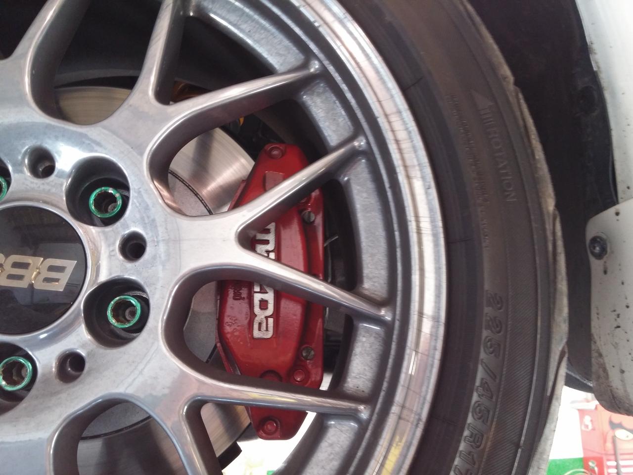
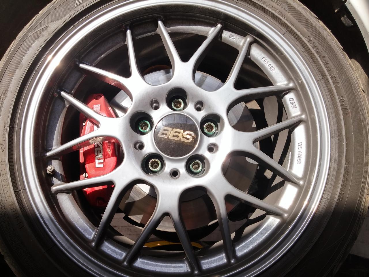
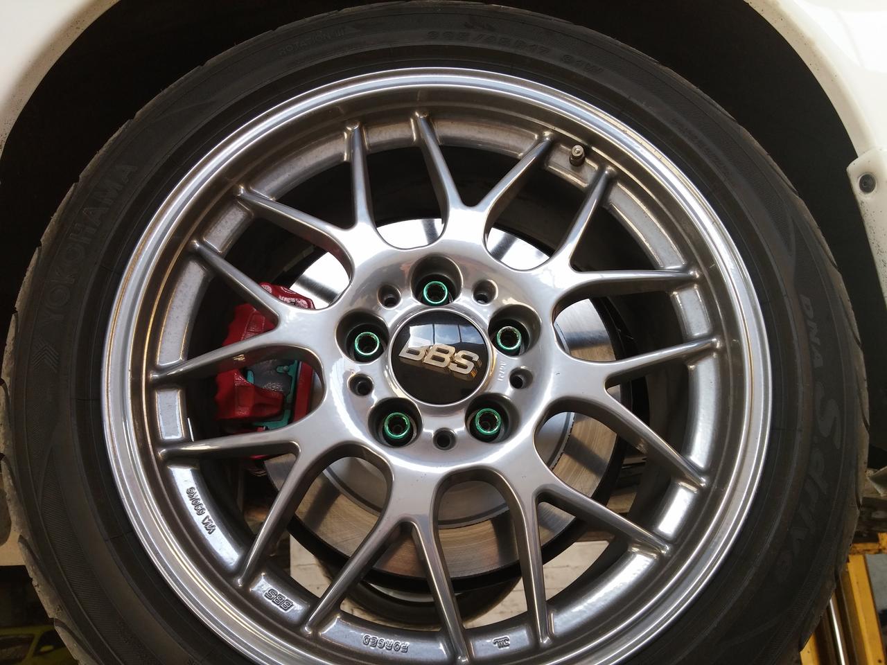
The calipers turned out much better than I expected and I really like the extra touch added by Hayward Rotary to show off the Mazda logo as I didn't think they would go that far! I never cleaned calipers before when I wash a car but now I'm going to have to consciously keep them clean!
Pads
http://www.project-mu.co.jp/en/products/pad_hcplus.html
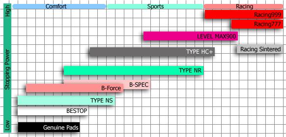
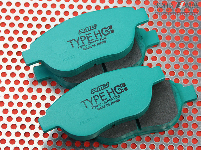
Thought I would try these as they were just about the same price as Ferodo's and Hawk's and were available from RHDJapan at the same time that I purchased the Dixcel rotors from them. We'll see how they do but with my little driving so far I can at least say they aren't noisy.
Brake Lines, Coilovers, Bushings
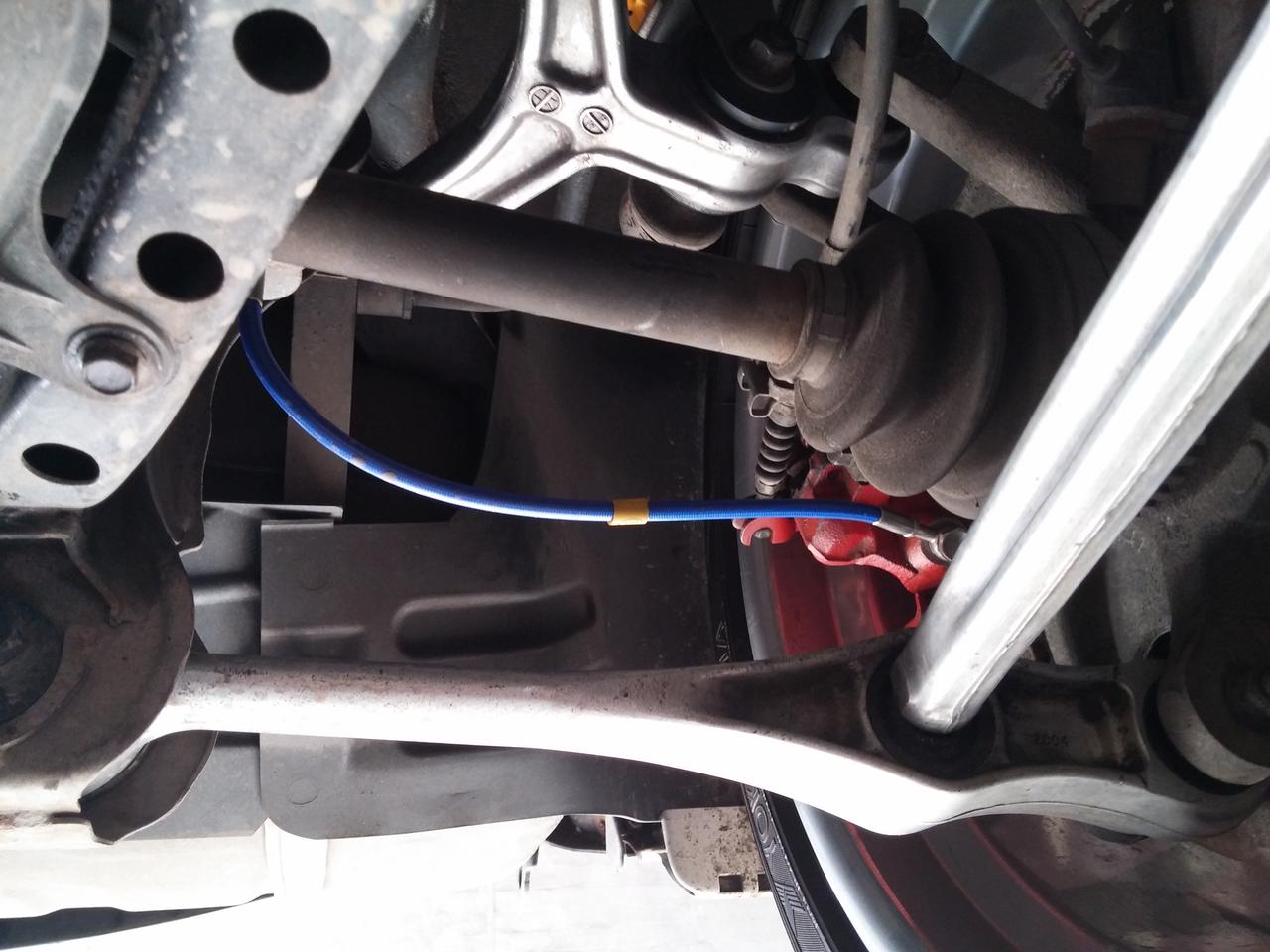
The new brake setup is crazy. The responsiveness of the pedal is 100x better than before although some of that could be due to my previous brakes being so poor.
The bushings look good and make no squeaky noises (thank god) and the ohlins just look so damn good. I'm going to end up jacking the car up each time I wash it to remove the wheels and clean them, lol.
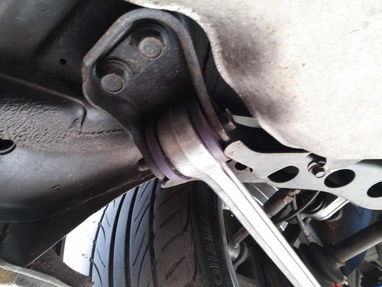
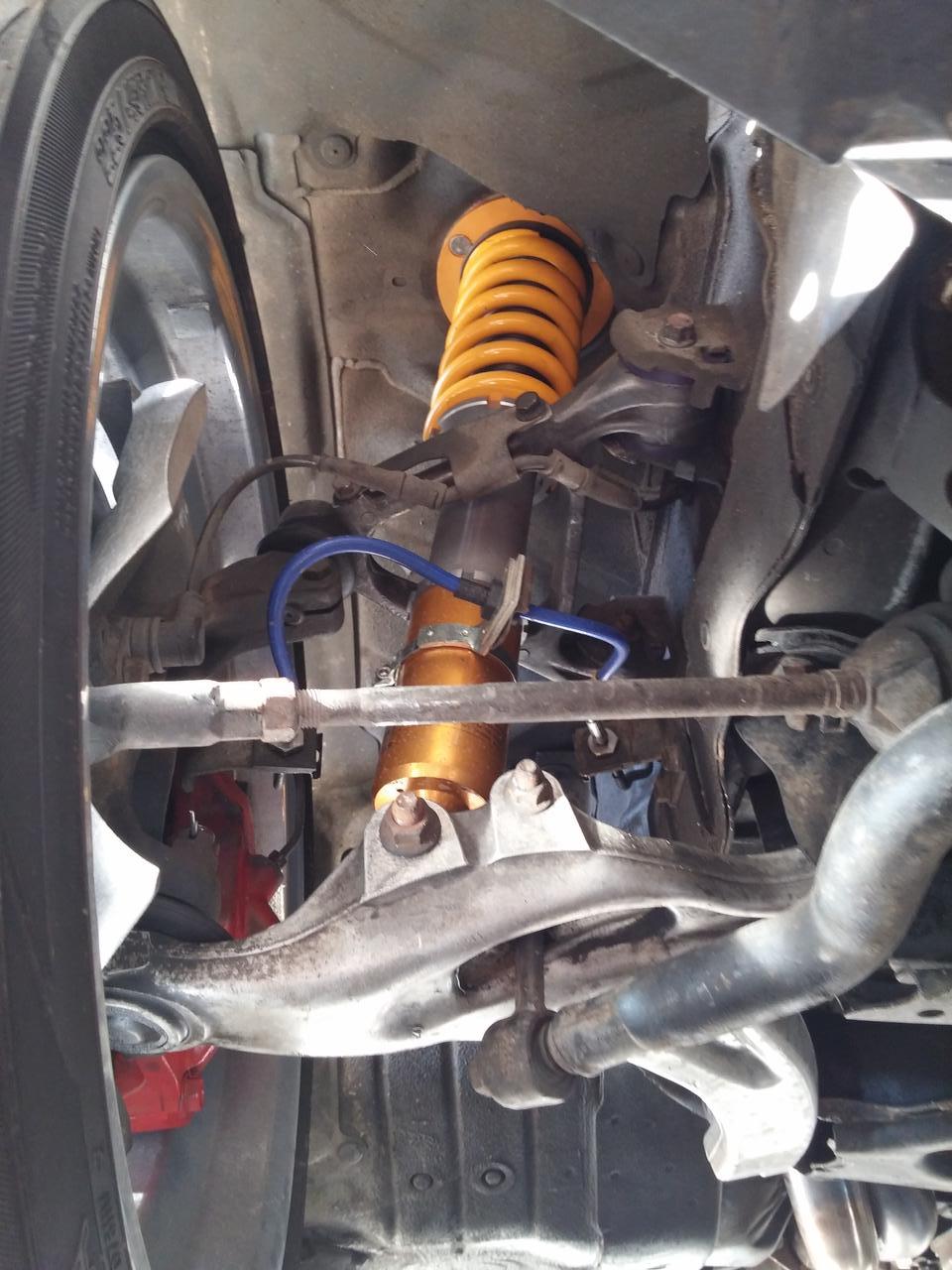
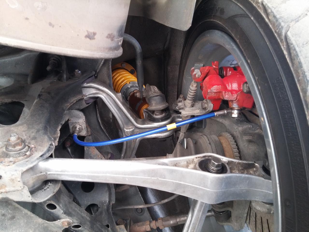
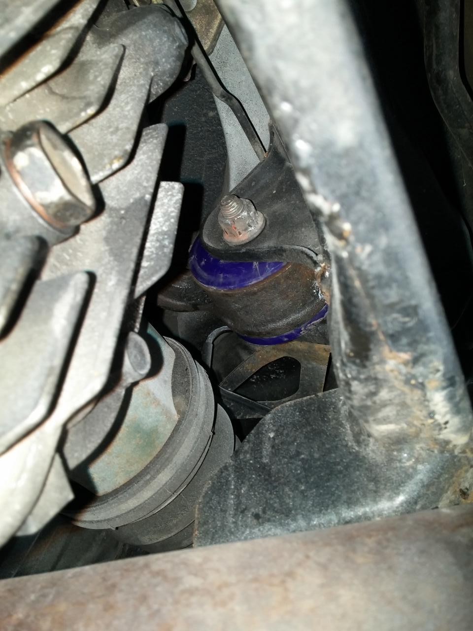
I promised photos and I have a couple to share of some of the obvious work that was completed. The car wasn't that clean as it had been driven and worked on for the last month but I will take photos of everything cleaned up and washed when the weather is better.
Brake Rotors, Calipers and Pads
Rotors
http://www.dixcel.co.jp/en/rotor/rotor_fcr.html
The new brake discs by Dixcel are the same size as the RS rotors that came off the car. The FP are the high performance model from Dixcel (at least for the FD) and have a 20% higher carbon content than their standard rotors. They are also heat treated for improvements in crack reistance and distortion and have an anti-corrosion coating (basically they are painted silver on the hub and outside of the rotor).
Standard Dixcel Discs
FP/FS (FS is slotted) Dixcel discs
Calipers
The calipers turned out much better than I expected and I really like the extra touch added by Hayward Rotary to show off the Mazda logo as I didn't think they would go that far! I never cleaned calipers before when I wash a car but now I'm going to have to consciously keep them clean!
Pads
http://www.project-mu.co.jp/en/products/pad_hcplus.html
Thought I would try these as they were just about the same price as Ferodo's and Hawk's and were available from RHDJapan at the same time that I purchased the Dixcel rotors from them. We'll see how they do but with my little driving so far I can at least say they aren't noisy.
Brake Lines, Coilovers, Bushings
The new brake setup is crazy. The responsiveness of the pedal is 100x better than before although some of that could be due to my previous brakes being so poor.
The bushings look good and make no squeaky noises (thank god) and the ohlins just look so damn good. I'm going to end up jacking the car up each time I wash it to remove the wheels and clean them, lol.
- Joined
- Jan 12, 2018
- Messages
- 1,415
February 2016
RE-Amemiya High Flow Cat and Knight Sports Downpipe
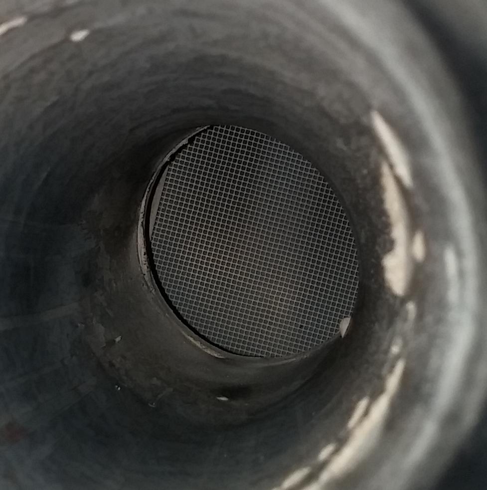
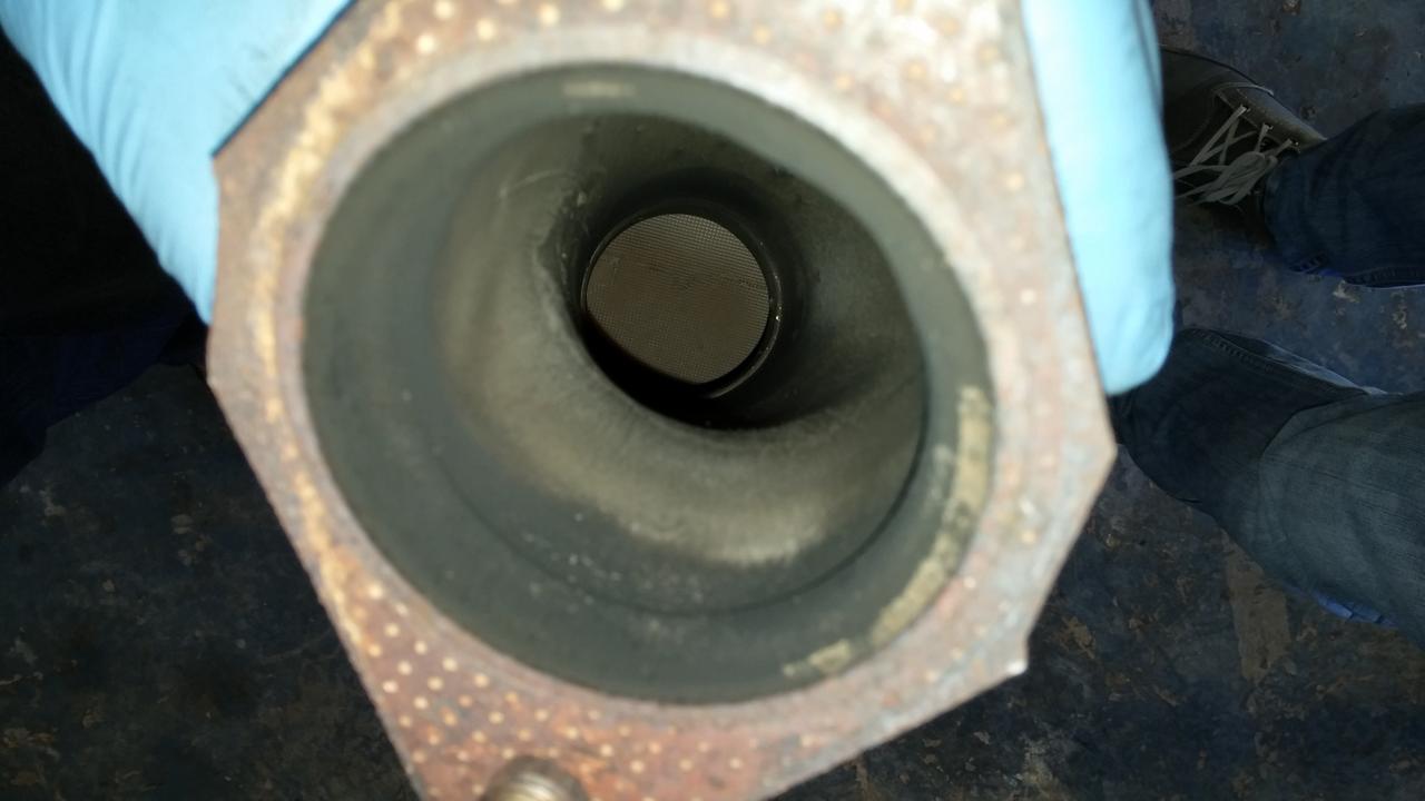
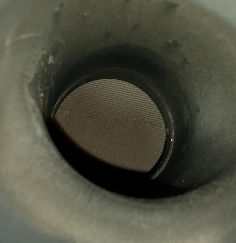
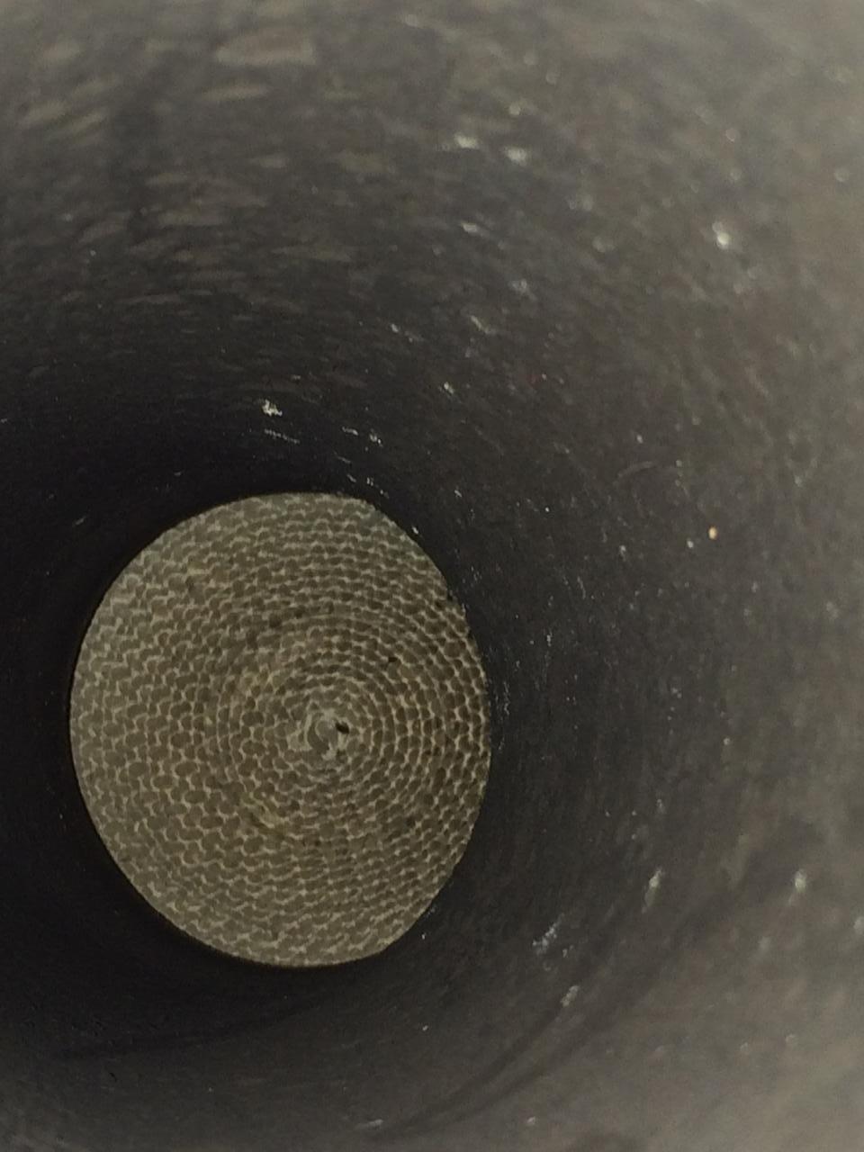
It turns out that my stock cat was cracked which was a shame as I didn't want to replace it and a brand new cat is very expensive. Luckily, I found a used one in good condition from another FDUKer. The RE-Amemiya is a very high flowing 3-inch unit at only 150-200 Cells Per Square Inch ("CPSI") and is way smaller and lighter than the stocker. Unfortunately, it is too unrestrictive as the car can't technically pass emissions with it. The hydrocarbons number is within the threshold at idle and fast idle but the carbon monoxide number is too high. Whilst this is a dissapointment, it is also pretty impressive that this cat which is much smaller in terms of total surface area of the stock cat honeycomb (let alone the higher 600-800 CPSI), is almost enough. I would reckon a 3-inch cat that is rated 300-400 CPSI could get the car to pass and honestly there wouldn't be any real horsepower loss going from 200 to 400 CPSI anyway.
Stock Cat With Photos of Cracks (Ceramic)
High Flow Cat - Notice the Difference in Density (Metallit)
High Flow Cat - Notice Air Pump Pipe Welded On
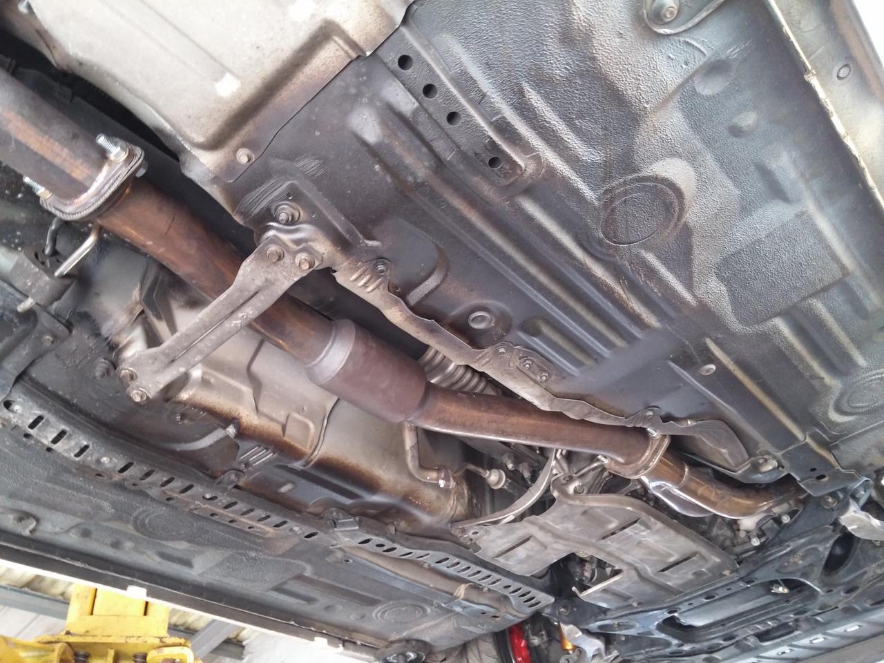
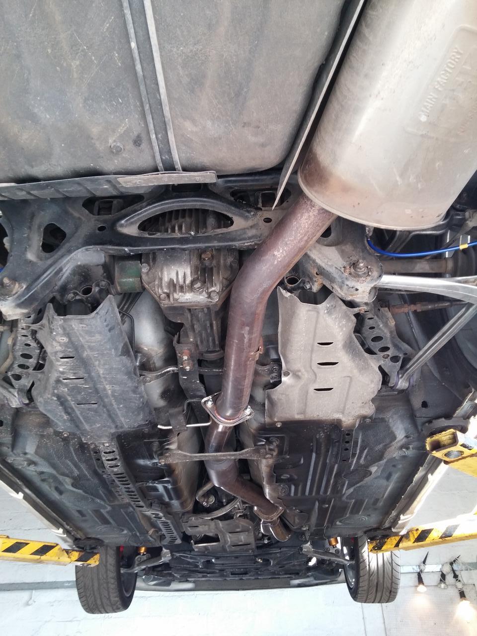
Apparently the Knight Sports downpipe was a royal pain in the ass to fit because of its shape and it was determined that undoing both engine mounts to raise the engine was the easiest way. It looks pretty sweet though but it's a shame no one will ever see it!
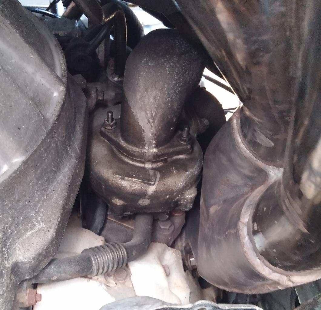
Up Close Shot of Rear Turbo
Previously we had noticed some wetness on the rear turbo. Carl cleaned it off and drove it around during mapping and boosting to see if oil would come back and fortunately none has shown up yet. I'm starting to think the turbos are actually fine and the oil on the turbos and drenching the intercooler piping was simply due to previous owner user error in overfilling the oil.
RE-Amemiya High Flow Cat and Knight Sports Downpipe
It turns out that my stock cat was cracked which was a shame as I didn't want to replace it and a brand new cat is very expensive. Luckily, I found a used one in good condition from another FDUKer. The RE-Amemiya is a very high flowing 3-inch unit at only 150-200 Cells Per Square Inch ("CPSI") and is way smaller and lighter than the stocker. Unfortunately, it is too unrestrictive as the car can't technically pass emissions with it. The hydrocarbons number is within the threshold at idle and fast idle but the carbon monoxide number is too high. Whilst this is a dissapointment, it is also pretty impressive that this cat which is much smaller in terms of total surface area of the stock cat honeycomb (let alone the higher 600-800 CPSI), is almost enough. I would reckon a 3-inch cat that is rated 300-400 CPSI could get the car to pass and honestly there wouldn't be any real horsepower loss going from 200 to 400 CPSI anyway.
Stock Cat With Photos of Cracks (Ceramic)
High Flow Cat - Notice the Difference in Density (Metallit)
High Flow Cat - Notice Air Pump Pipe Welded On
Apparently the Knight Sports downpipe was a royal pain in the ass to fit because of its shape and it was determined that undoing both engine mounts to raise the engine was the easiest way. It looks pretty sweet though but it's a shame no one will ever see it!
Up Close Shot of Rear Turbo
Previously we had noticed some wetness on the rear turbo. Carl cleaned it off and drove it around during mapping and boosting to see if oil would come back and fortunately none has shown up yet. I'm starting to think the turbos are actually fine and the oil on the turbos and drenching the intercooler piping was simply due to previous owner user error in overfilling the oil.
- Joined
- Jan 12, 2018
- Messages
- 1,415
February 2016
Braided Clutch Hose, HKS Twin Power, Radiator, Old Rats Nest Hoses and Splits
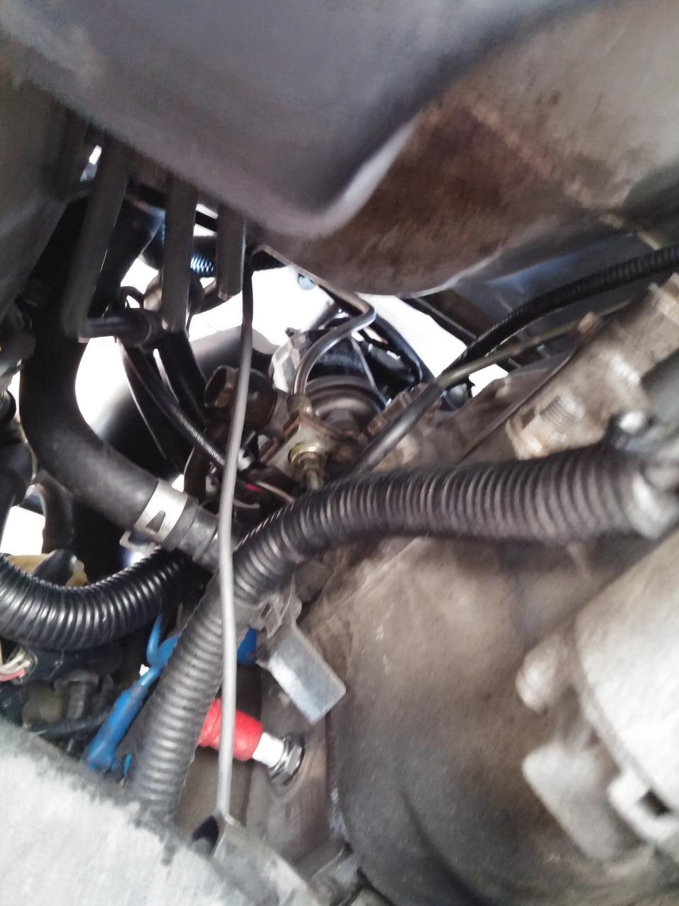
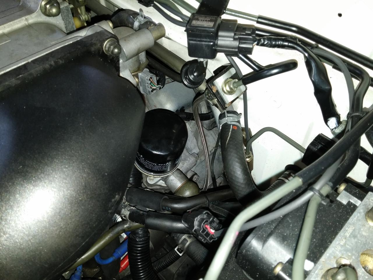
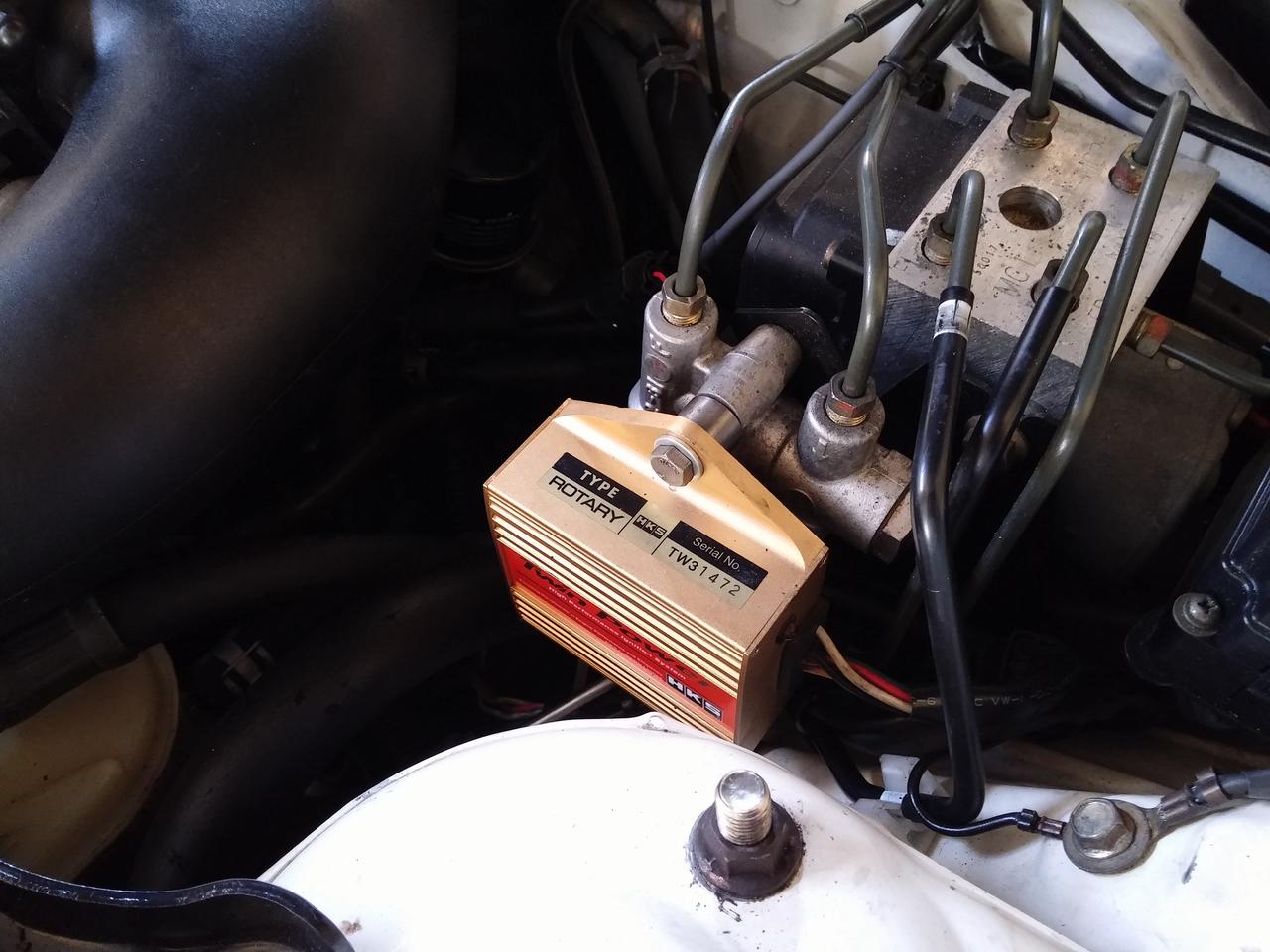
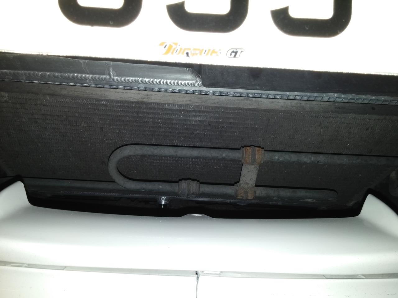
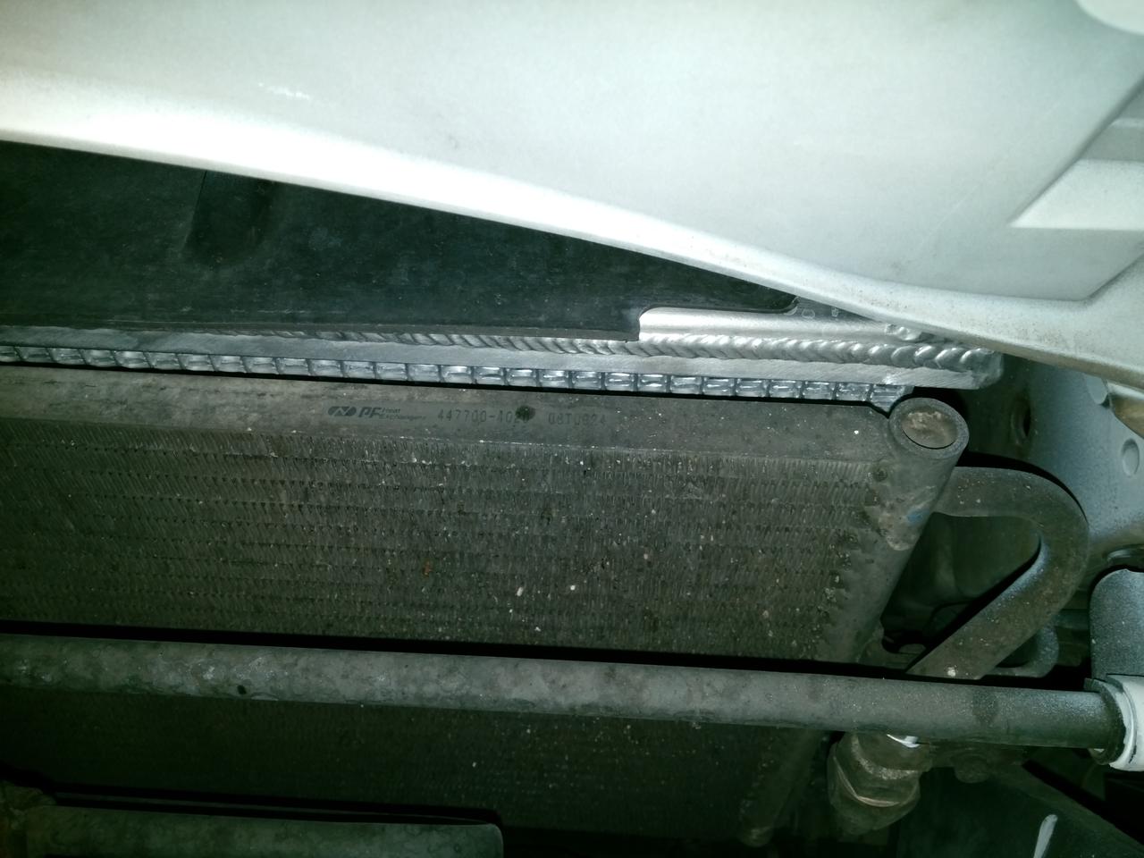
I couldn't get a better shot of the radiator but it's there as you can sorta see! lol.
Split Hoses
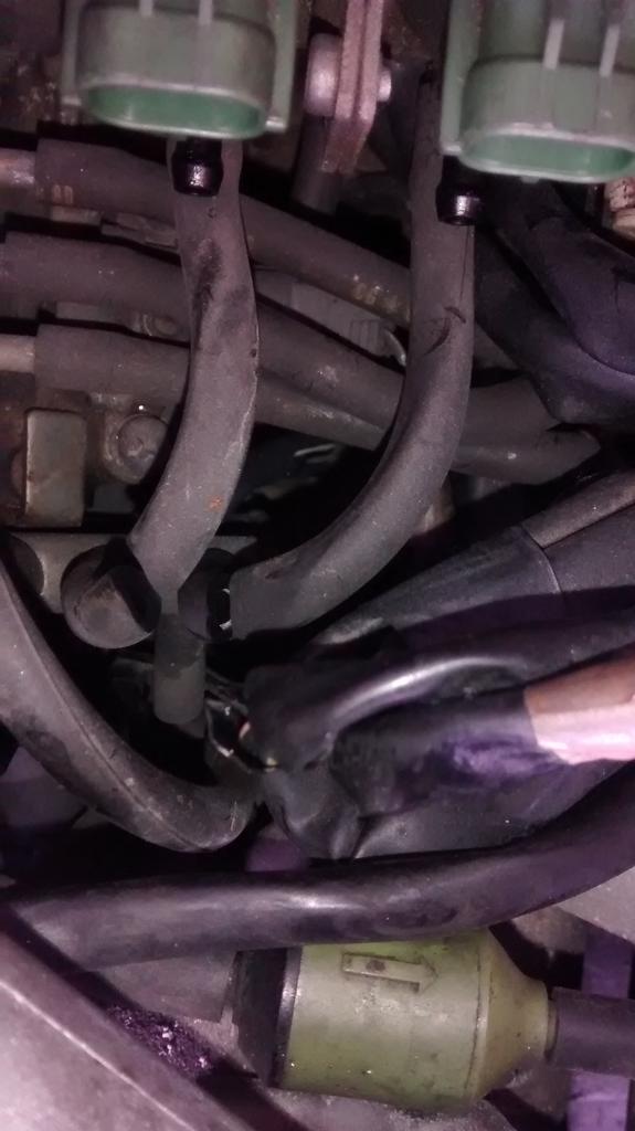
Brittle Hoses
I can literally break these with just a little bit of force trying to bend them. I'm glad this was caught and got done.
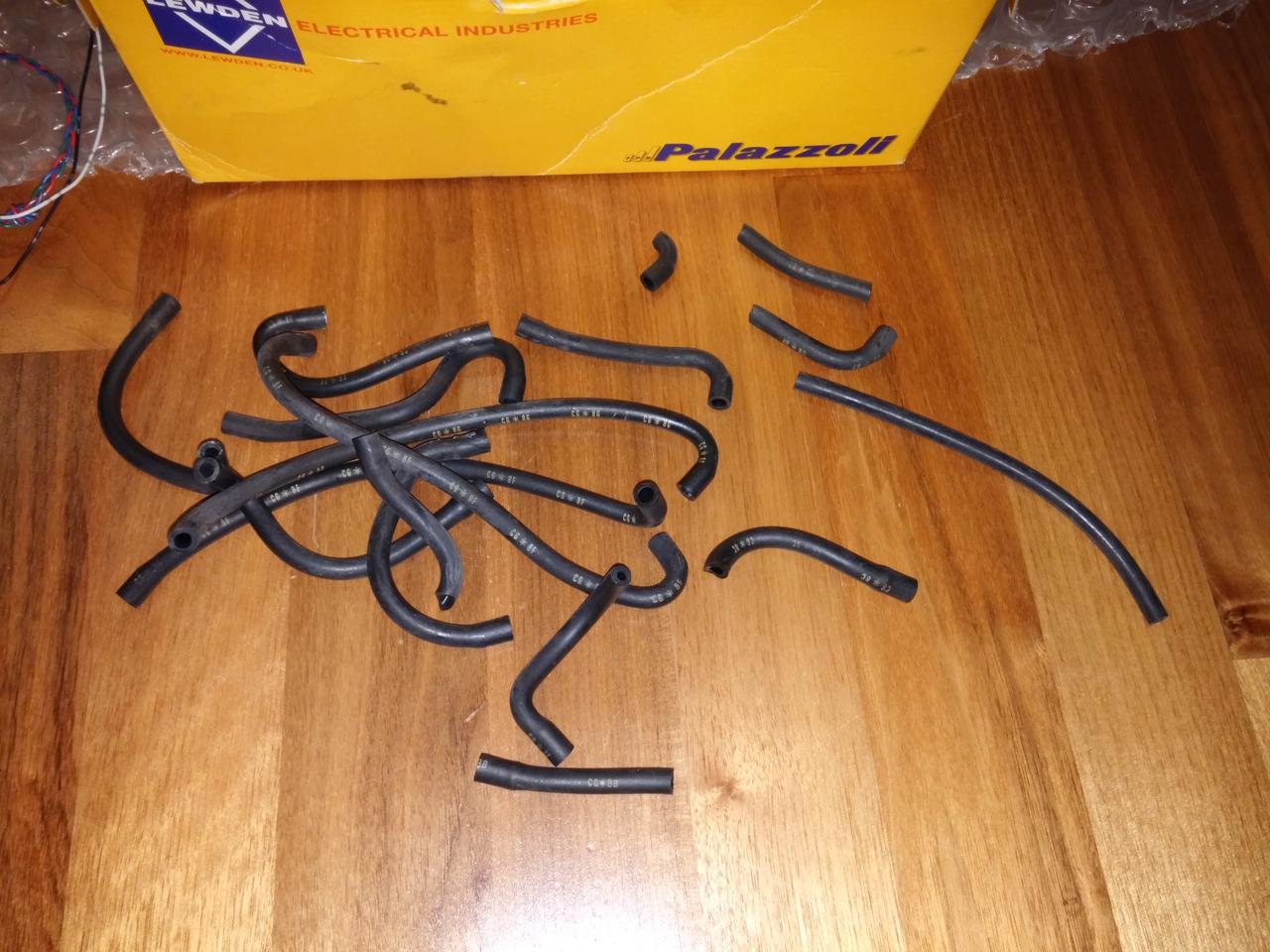
Braided Clutch Hose, HKS Twin Power, Radiator, Old Rats Nest Hoses and Splits
I couldn't get a better shot of the radiator but it's there as you can sorta see! lol.
Split Hoses
Brittle Hoses
I can literally break these with just a little bit of force trying to bend them. I'm glad this was caught and got done.
- Joined
- Jan 12, 2018
- Messages
- 1,415
February 2016
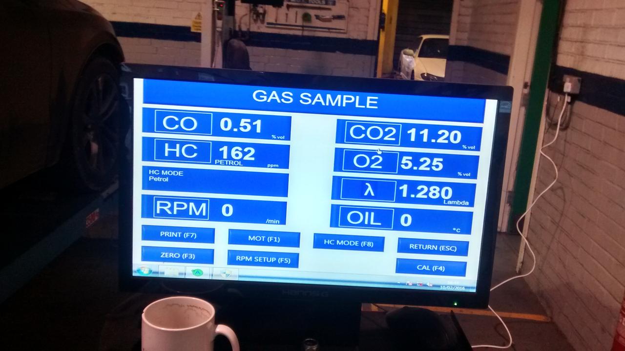
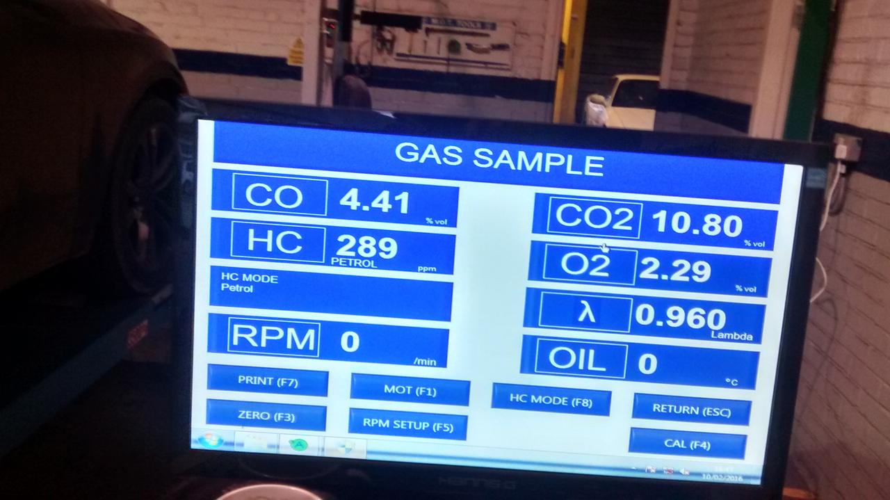
Emissions Results - Lol
For all of you FDUKers out there I thought I would share the results of a test I got done with the high flow cat on the car. Based on these numbers I think a high flow cat with about 400 Cells Per Square Inch ("CPSI") would actually pass and would still be a lot less restrictive than the stock cat. This is not based on science, just a hunch.
I'm pretty sure my targets are based on the generic catalyst requirements since my import doesn't fall under the UK Mazda RX-7 regulations. Either way, the required results aren't that far off from each other but what I should have for a 1995-2002 vehicle is:
Normal Idle
Carbon Monoxide ("CO") - 0.5% (UK RX-7 limit - 0.5%)
Hydrocarbon ("HC") - No requirement (UK RX-7 limit - No requirement)
Raised Engine Speed (c.2,500 RPM)
CO - 0.3% (UK RX-7 limit - 0.3%)
HC - 0.02% or 200ppm (UK RX-7 limit - 0.02% or 200ppm)
Lambda - 1 +/- 0.03 (UK RX-7 limit - 0.97 to 1.6)
Idle
Raised Engine Speed (c.2,500 RPM)
Emissions Results - Lol
For all of you FDUKers out there I thought I would share the results of a test I got done with the high flow cat on the car. Based on these numbers I think a high flow cat with about 400 Cells Per Square Inch ("CPSI") would actually pass and would still be a lot less restrictive than the stock cat. This is not based on science, just a hunch.
I'm pretty sure my targets are based on the generic catalyst requirements since my import doesn't fall under the UK Mazda RX-7 regulations. Either way, the required results aren't that far off from each other but what I should have for a 1995-2002 vehicle is:
Normal Idle
Carbon Monoxide ("CO") - 0.5% (UK RX-7 limit - 0.5%)
Hydrocarbon ("HC") - No requirement (UK RX-7 limit - No requirement)
Raised Engine Speed (c.2,500 RPM)
CO - 0.3% (UK RX-7 limit - 0.3%)
HC - 0.02% or 200ppm (UK RX-7 limit - 0.02% or 200ppm)
Lambda - 1 +/- 0.03 (UK RX-7 limit - 0.97 to 1.6)
Idle
Raised Engine Speed (c.2,500 RPM)
- Joined
- Jan 12, 2018
- Messages
- 1,415
February 2016
**Kananent Double DIN Bracket Photos for Those That Asked**
Like I said a couple of pages back, the Kananet UA-T39D is the only double din unit designed to fit the FD Mazda RX-7. It is literally only available from Japan and will cost you about £70-75 in total to purchase, ship and pay customs taxes for in order to get it to your door here in the UK. However, in my opinion the fit is almost as good as if it were from the Mazda factory.
I will try to get some photos in the daytime tomorrow to better show off how it looks in the car as the flash on my phone kinda messes things up.
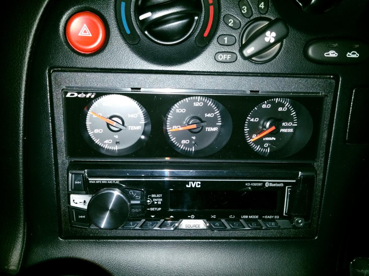
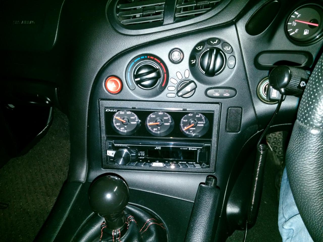
**Kananent Double DIN Bracket Photos for Those That Asked**
Like I said a couple of pages back, the Kananet UA-T39D is the only double din unit designed to fit the FD Mazda RX-7. It is literally only available from Japan and will cost you about £70-75 in total to purchase, ship and pay customs taxes for in order to get it to your door here in the UK. However, in my opinion the fit is almost as good as if it were from the Mazda factory.
I will try to get some photos in the daytime tomorrow to better show off how it looks in the car as the flash on my phone kinda messes things up.
- Joined
- Jan 12, 2018
- Messages
- 1,415
February 2016
How Does the Car Drive So Far?
I have only driven about 100 miles so far but I will try to convey my thoughts so far in this post. So long as it doesn't rain on Sunday, I will be doing my first track day at Snetterton as it's tied with Oulton Park as my favourite circuit. I plan to take it easy and just learn more about the car's dynamics (and hopefully not crash!), but after that experience I will post an updated driving impression.
Today consisted of a lot of street cruising on little B roads and the highway with a couple of WOT pulls.
Suspension and Brakes
Coilovers
The first thing I noticed when Carl picked me up at the train station and I was sitting in the passenger seat was the effect of the Ohlins compared to my old setup. At my request, the Ohlins were left at the out of the box ride height and damper settings (which are about in the middle of the adjustment range from soft to hard).
After doing quite a bit of reading on the American forums where they generally prefer a 10/8 setup for a street car that occassionally sees a track day, I was a bit worried about 11kg springs front and rear on the Ohlins. However, whilst the ride is firm it is not uncomfortable at all (in fact I may make it a bit firmer!) because the dampers respond so quickly to all sorts of bumps. The car never seems to get out of sorts even if you are accelerating and hit a bump in the road. One thing I have noticed is that the dampers are sublime above about 50 mph in that you might as well be driving an Audi RS6 or something as it's that good. Below 50 mph they don't absorb the bumps as well but it's still much better than my previous setup at low speeds and I would imagine much better than stock FD shocks/springs or other lesser coilovers.
Bushings
My main worry was that they would squeak like a son of a bitch but they don't.
My second worry was that they would make the car too stiff, vibrate the chassis too much, and transmit excess noise into the car. But they don't.
I'm not sure what sort of performance benefits I can talk about yet with them but so far I have nothing negative to say about them other than I'm glad the differential bushings were done as there is no more clunking when shifting! My old diff bushings were toast.
Brakes
Holy shit! The whole setup is excellent compared to what was on the car before. Pedal response reminds me of a Volkswagen in that you touch the pedal and the car wants to start slowing down, rather than how it is on other Mazdas (and Ford's actually) where you have to press the pedal about 1/4-1/2 way before anything really happens.
I have only stopped aggressively twice so far as it's unsafe to do so on a public road with someone behind you, but the pads bite instantly and the car certainly stops quickly. Hopefully the pads won't be too dusty but I already like them way better than the EBC Yellowstuff I had on my RX-8 (those were absolute trash).
I'm looking forward to seeing how well the car stops on the track.
Clutch and Transmission
The clutch pedal is definitely better than it was before with the replaced master and slave. Nice and progressive with actual feeling if that makes any sense.
The new Millers nano-tech transmission and diff oil seems to be a step up from what was in it before but I do still occassionally get a grind when I shift into 2nd gear so I'm pretty sure the synchro is on its way out.
I have never checked the clutch but I'm sure it's the stock unit with over 50,000 miles on it or something so it probably won't last much longer.
Engine and Map
The idle is c.100 RPM higher than it was on the stock ECU (850 vs 750) but as a result the car doesn't fluctuate so much like it did on the stock ECU between 750 or 1000 RPM.
It is very obvious that the car has a lot more power below 2500 RPM when cruising around, even when not in boost. Putting around is a lot easier.
On boost the car is much different than it was on the stock ECU, and not just because it has more power. On the stock ECU the car would pull very hard on the primary jerk into the secondary, pull similarly hard as it did on the primary until about 6,000-6,500 RPM and then fall flat on its face although it would rev out to 8,000. On the new ECU and tune, the car pulls very strongly from below 3,000 RPM to the transition somewhere around 4,500-5,000 RPM, and then there is no jerk when the secondary comes on. But then it pulls like a fucking train and it doesn't seem to tail off until maybe 7,500-7,800 RPM. I definitely prefer the way the twins interact now than how they did on the stock ECU. The whole RPM range is vastly improved and I would be curious to see what the power and torque curves look like.
As for power, the car is obviously quicker everywhere and is probably the fastest car I've ever owned in terms of straight line speed.
For information, the boost is set to about 0.85 bar and injector duty cycle on the stock fuel pump with no voltage mod is around 88-89%.
Cooling
Twin oil coolers are efficient! Oil temps when driving are 60 or lower and in traffic about 80.
The new radiator is about 10 degrees cooler on the highway than the stocker although I think the old thermostat was on its way out as well. Temps in this cold February weather are about 75 on the highway and 80-85 in the city.
- Joined
- Jan 12, 2018
- Messages
- 1,415
February 2016
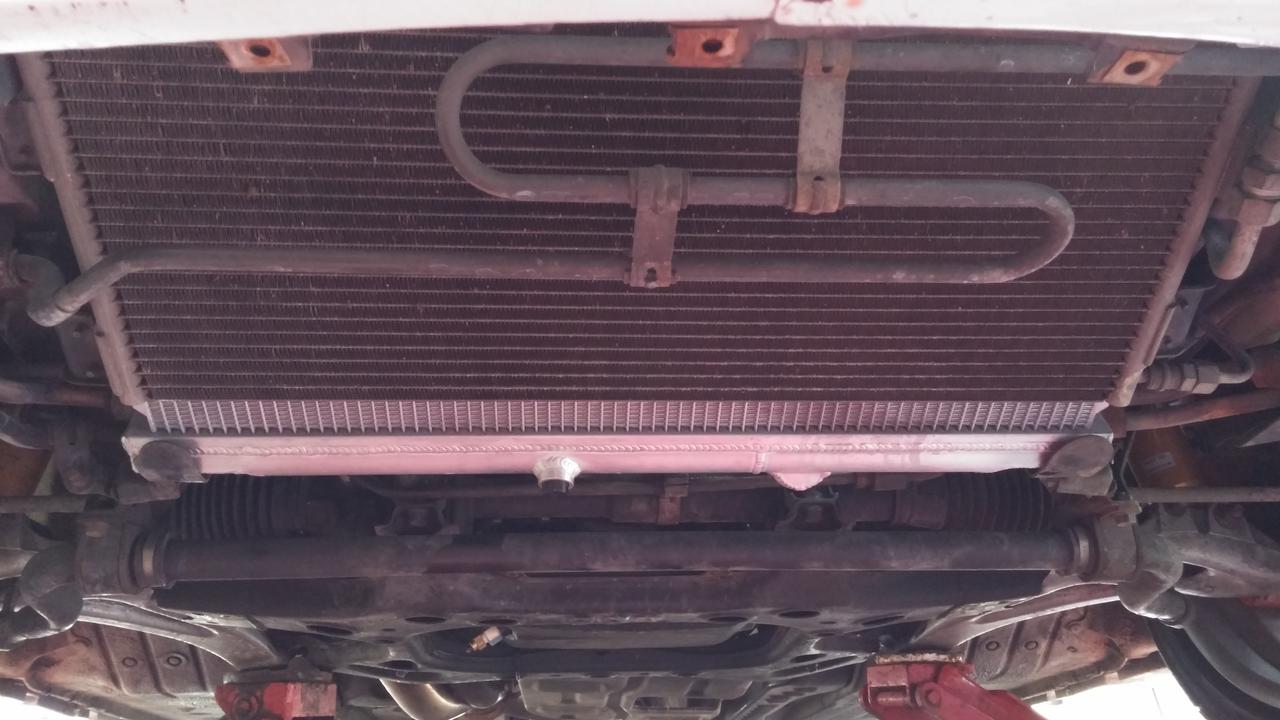
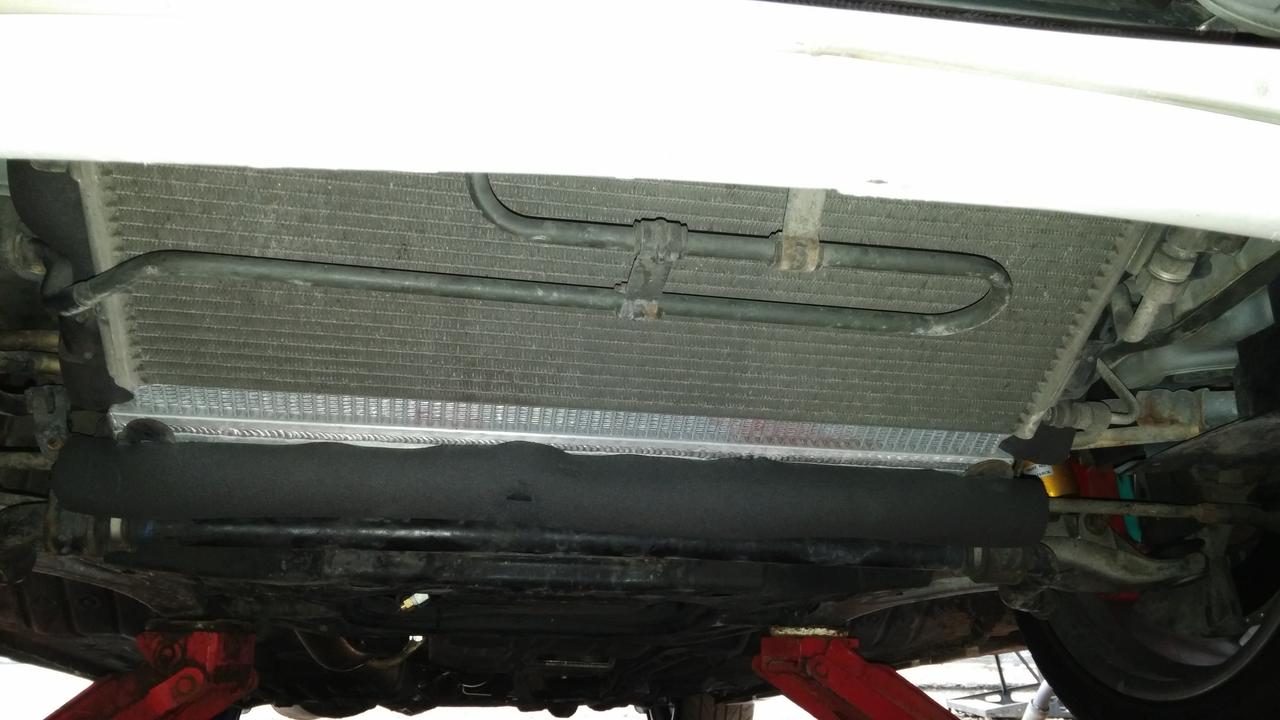
Yesterday, I took my car to Essex Rotary to have some cheapo but effective neoprene radiator ducting fitted to seal below and seal the sides of the new Koyo radiator, modify my seat rails, and mount my water injection pump on the car because I didn't know where to put it given the lack of space underneath my car due to the factory engine bay, A/C, power steering, etc.
Pics of Koyo Radiator Before and After Ducting
Before Ducting
After Ducting (but before undertray was put back on (which shows ducting and sealing better)
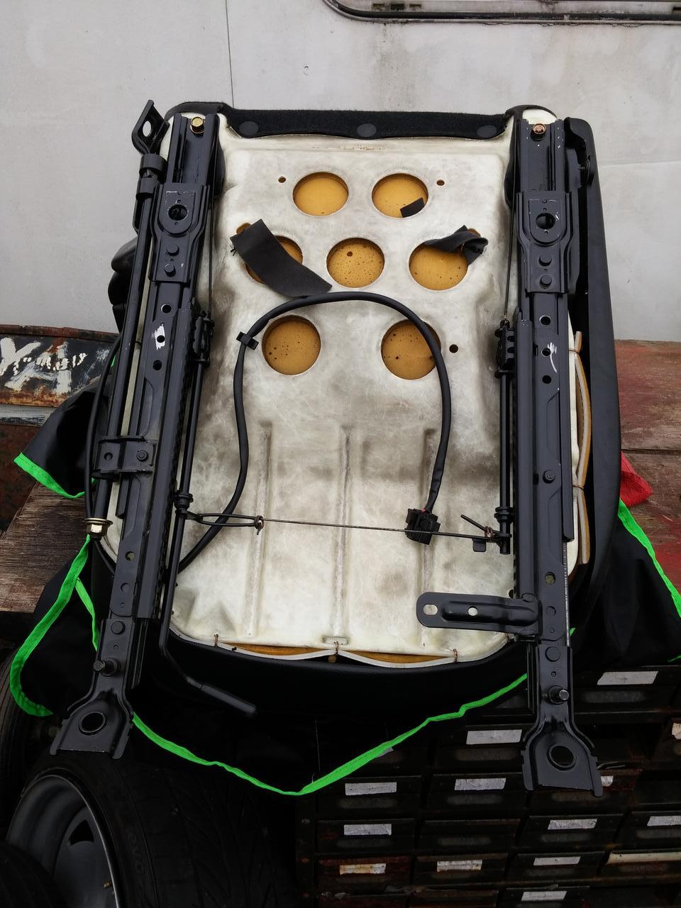
Seat Rails
On the driver's side we followed Dark Knight's How-to and removed the Japanese stopper to extend the rails to the UK, US and AUS spec which is 3 clicks before full lock. Then we took out the second stopper which moves the rails to the end of the adjustment range. We determined that the adjustment sliders are not in anyway structural and thus the rails themselves are still just as safe as they were before the modification.
On the passenger side I only modified the rail to UK spec since that will be fine for most people as I felt comfortable with the Japanese rail when I sat in the passenger seat and I am 6'2".
We even touched up the rails to make sure they were all black unlike in the below photo.
As for the difference, HOLY CRAP it's amazing. It's now much easier to get into and out of the car and the driving position is way better. My legs are comfortably stretched and in fact the clutch pedal is now too far away if the seat is all the way back! I have tons of more leg room, can heel & toe and I can see all of the gauges and the entire RPM and speedo gauges for the first time without dipping my head! All I need to do now is get a snap off steering wheel boss to bring the wheel a tad closer to me as my arms are pretty stretched out now and I prefer to have them bent slightly.
Water Injection Pump Install
The main reason I brought this car to Aston was to find out where and how to mount the AEM water injection pump in the car so that it would still be level and/or lower than the bottom of the windshield wiper reservoir tank that I will be using. Unlike a lot of other guys that run water injection in the FD, my car is still completely stock in terms of engine bay configuration with power steering and A/C (both of which I will never remove) and thus it was difficult to find a good spot. What made it more difficult was that I didn't want it installed in the back of the car near the rear washer bottle as I didn't want the pain in the ass of wiring and running hose all the way to the front.
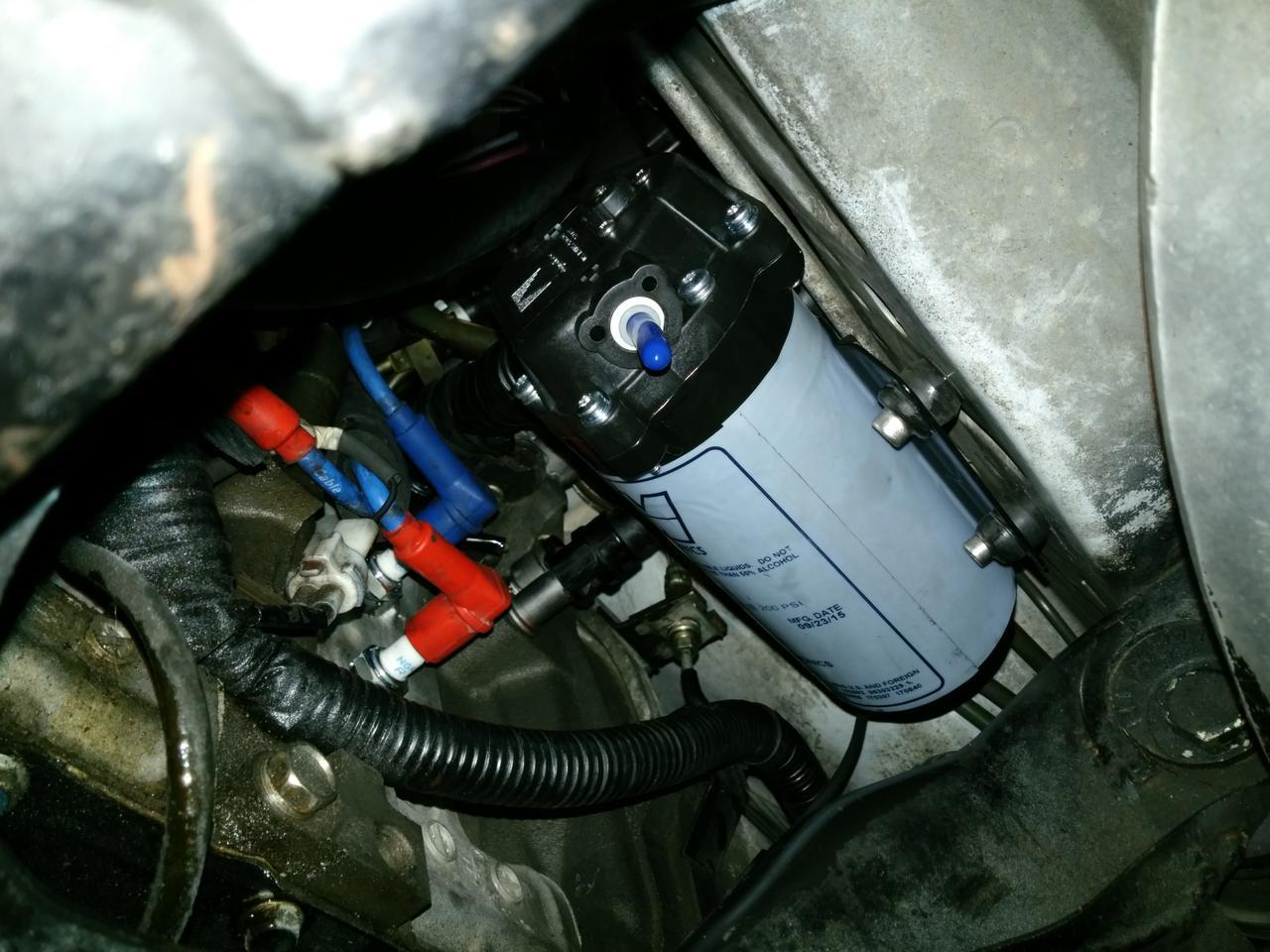
I saw a How-to on the American forum for installing the water injection kit to the chassis rail on the passenger side near the spark plugs. Unfortunately, that How-to involved fabricating a bracket and welding it to the frame which we thought might be tricker than the guide made out given the lack of space. However, Aston applied his mind and figured he could use the stock AEM bracket to screw it into the frame rail. He noticed that two of the four holes in the bracket exactly matched holes that were already in the frame, and for the other holes on top of the pump he could basically tap the frame and thread it to match.
Tapping the frame and making the right threads turned out to be a royal pain in the ass because of the lack of space in there but somehow Aston managed after a couple of hours and we had the pump bolted to the frame using the stock rubber anti-vibration stoppers! The pump sits pretty close to the spark plugs but they seem to still be accessible if a bit more difficult to access. I really like it because it is very discreet and it is mounted about level/slightly below the washer bottle. Check out the photo below to get an idea of where it is. The oil you see is from spilling when doing oil changes and isn't a leak in the sump or anything.
AEM 250cc/min Nozzle Tap into Throttle Body Elbow
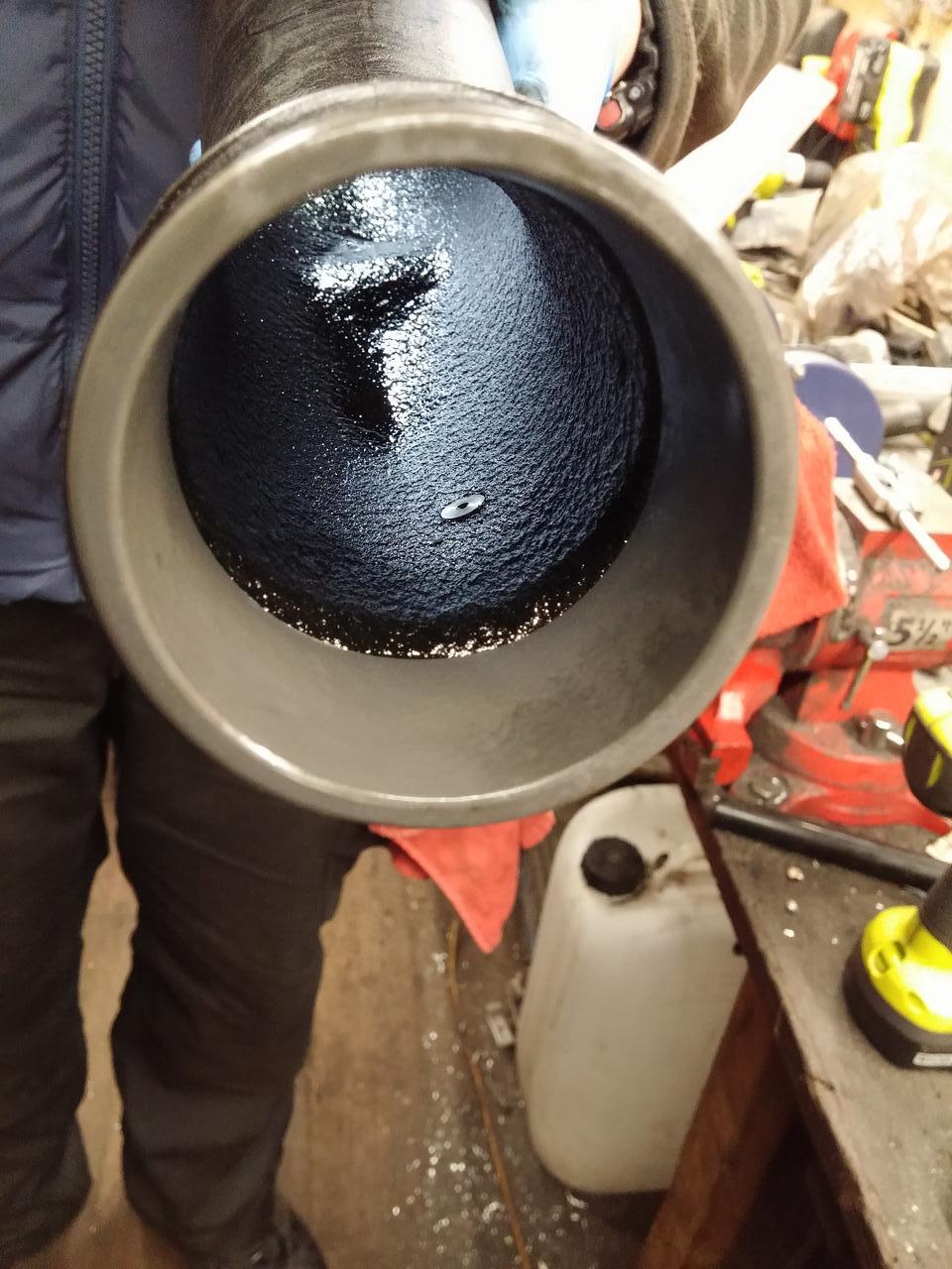
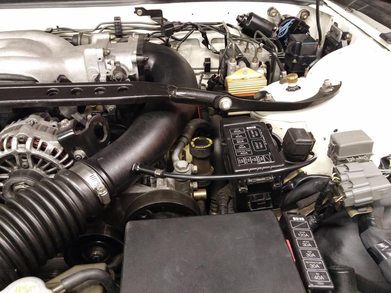
It was getting late and the sun had already set so Aston couldn't finish the water injection install today, but he offered to at least tap the throttle body elbow, create a 1/8" NPT thread and route the 1/4" nylon tubing from the nozzle to the pump below. This is actually alright because all I need to do now is drill two 7/8" holes in the washer reservoir for the self-sealing feed tap and the self-sealing leveling sensor before tackling the electrics which I am pretty comfortable with doing on my own.
We debated for a little bit on where to tap the elbow and decided it made more sense to tap closer to the intercooler rather than closer to the throttle body. We took off the elbow and the pipes were shiny with oil but what can you do? It doesn't really affect performance so I'm not too fussed about it, although the perfectionist in me would like to drench all of the pipes and intercooler in brake cleaner and dry it all out...
Below is a photo of the inside of the throttle body elbow with the nozzle tap and another photo of how it looks in the engine bay.
Overall, I'm very happy with the ducting on the radiator, I love the extra leg room from the seat modification and I'm stoked about the water injection pump location and location of the injection nozzle.
I've used Aston a few times in the past when I had my RX-8 and he has never dissapointed. Aston exhibits very good attention to detail and good creativity, in particular when figuring out a way to mount the water injection pump. I'm very grateful for his assistance today and would recommmend guys in the Essex/London area to pay him a visit if you need some work done. It is also nice that he has access to some very hard to find parts such as Idemitsu oils and premix, R-Magic, Greddy, Cusco, Racing Beat, Royal Purple, Carbon Cooling, Competition Clutch, Black Halo Racing, etc in which he has direct trader relationships with these companies to import and sell products throughout Europe.
Yesterday, I took my car to Essex Rotary to have some cheapo but effective neoprene radiator ducting fitted to seal below and seal the sides of the new Koyo radiator, modify my seat rails, and mount my water injection pump on the car because I didn't know where to put it given the lack of space underneath my car due to the factory engine bay, A/C, power steering, etc.
Pics of Koyo Radiator Before and After Ducting
Before Ducting
After Ducting (but before undertray was put back on (which shows ducting and sealing better)
Seat Rails
On the driver's side we followed Dark Knight's How-to and removed the Japanese stopper to extend the rails to the UK, US and AUS spec which is 3 clicks before full lock. Then we took out the second stopper which moves the rails to the end of the adjustment range. We determined that the adjustment sliders are not in anyway structural and thus the rails themselves are still just as safe as they were before the modification.
On the passenger side I only modified the rail to UK spec since that will be fine for most people as I felt comfortable with the Japanese rail when I sat in the passenger seat and I am 6'2".
We even touched up the rails to make sure they were all black unlike in the below photo.
As for the difference, HOLY CRAP it's amazing. It's now much easier to get into and out of the car and the driving position is way better. My legs are comfortably stretched and in fact the clutch pedal is now too far away if the seat is all the way back! I have tons of more leg room, can heel & toe and I can see all of the gauges and the entire RPM and speedo gauges for the first time without dipping my head! All I need to do now is get a snap off steering wheel boss to bring the wheel a tad closer to me as my arms are pretty stretched out now and I prefer to have them bent slightly.
Water Injection Pump Install
The main reason I brought this car to Aston was to find out where and how to mount the AEM water injection pump in the car so that it would still be level and/or lower than the bottom of the windshield wiper reservoir tank that I will be using. Unlike a lot of other guys that run water injection in the FD, my car is still completely stock in terms of engine bay configuration with power steering and A/C (both of which I will never remove) and thus it was difficult to find a good spot. What made it more difficult was that I didn't want it installed in the back of the car near the rear washer bottle as I didn't want the pain in the ass of wiring and running hose all the way to the front.
I saw a How-to on the American forum for installing the water injection kit to the chassis rail on the passenger side near the spark plugs. Unfortunately, that How-to involved fabricating a bracket and welding it to the frame which we thought might be tricker than the guide made out given the lack of space. However, Aston applied his mind and figured he could use the stock AEM bracket to screw it into the frame rail. He noticed that two of the four holes in the bracket exactly matched holes that were already in the frame, and for the other holes on top of the pump he could basically tap the frame and thread it to match.
Tapping the frame and making the right threads turned out to be a royal pain in the ass because of the lack of space in there but somehow Aston managed after a couple of hours and we had the pump bolted to the frame using the stock rubber anti-vibration stoppers! The pump sits pretty close to the spark plugs but they seem to still be accessible if a bit more difficult to access. I really like it because it is very discreet and it is mounted about level/slightly below the washer bottle. Check out the photo below to get an idea of where it is. The oil you see is from spilling when doing oil changes and isn't a leak in the sump or anything.
AEM 250cc/min Nozzle Tap into Throttle Body Elbow
It was getting late and the sun had already set so Aston couldn't finish the water injection install today, but he offered to at least tap the throttle body elbow, create a 1/8" NPT thread and route the 1/4" nylon tubing from the nozzle to the pump below. This is actually alright because all I need to do now is drill two 7/8" holes in the washer reservoir for the self-sealing feed tap and the self-sealing leveling sensor before tackling the electrics which I am pretty comfortable with doing on my own.
We debated for a little bit on where to tap the elbow and decided it made more sense to tap closer to the intercooler rather than closer to the throttle body. We took off the elbow and the pipes were shiny with oil but what can you do? It doesn't really affect performance so I'm not too fussed about it, although the perfectionist in me would like to drench all of the pipes and intercooler in brake cleaner and dry it all out...
Below is a photo of the inside of the throttle body elbow with the nozzle tap and another photo of how it looks in the engine bay.
Overall, I'm very happy with the ducting on the radiator, I love the extra leg room from the seat modification and I'm stoked about the water injection pump location and location of the injection nozzle.
I've used Aston a few times in the past when I had my RX-8 and he has never dissapointed. Aston exhibits very good attention to detail and good creativity, in particular when figuring out a way to mount the water injection pump. I'm very grateful for his assistance today and would recommmend guys in the Essex/London area to pay him a visit if you need some work done. It is also nice that he has access to some very hard to find parts such as Idemitsu oils and premix, R-Magic, Greddy, Cusco, Racing Beat, Royal Purple, Carbon Cooling, Competition Clutch, Black Halo Racing, etc in which he has direct trader relationships with these companies to import and sell products throughout Europe.

- Joined
- Jan 10, 2018
- Messages
- 754
Awsome build man, WMI Port there will almost defiantly hit the other side of your pipe causing droplets. shouldn't be much of a problem although it would be more efficient at an angle towards the TB or on the bend pointing to the TB. Each to there own. Also Hold back from using wmi too much as the methanol breaks down lubricating oils causing more wear on the housings. Id also recommend an under tray if your going on track as air isnt going to want to flow through your rad as much at present. It wont show weakness in traffic or on motorway but track is a different ballgame all together  Oil temps are never really an issue. too cold is bad to hot is bad. you might see 125deg on track but that sorta temp is the upper side of fine good luck on your track day. the fds dominate everything even at 300bhpish
- Joined
- Jan 12, 2018
- Messages
- 1,415
Lol, these posts are from 2016 Gavbey! You might have a point about the water injection location but my thought was to inject earlier rather than right near the throttle body to allow more time for atomisation. In any case, I have been running it this way for two years and no issues yet. I am only injecting a maximum of 250cc/min (the smallest AEM nozzle in the kit) when at maximum boost. When not WOT it will inject less or sometimes none at all if I don't get to at least c.8-10 PSI. I also only use distilled water. No meth.
And of course I have the stock undertray. I would never drive around without it!
And of course I have the stock undertray. I would never drive around without it!
- Joined
- Jan 10, 2018
- Messages
- 754
Lol, these posts are from 2016 Gavbey! You might have a point about the water injection location but my thought was to inject earlier rather than right near the throttle body to allow more time for atomisation. In any case, I have been running it this way for two years and no issues yet. I am only injecting a maximum of 250cc/min (the smallest AEM nozzle in the kit) when at maximum boost. When not WOT it will inject less or sometimes none at all if I don't get to at least c.8-10 PSI. I also only use distilled water. No meth.
And of course I have the stock undertray. I would never drive around without it!
sweet ma bruda. water alone is fine den
 yeah like you say you want it early enough to pull the heat out of the air.
Yeah dude I drove my car for years without an under tray. I noticed a hugeeee amount of difference. ya been hitting the track then?
- Joined
- Jan 12, 2018
- Messages
- 1,415
February 2016 - Eventually replaced bulbs with OEM 2w
Today I replaced a tail light bulb, polished and waxed the car and I also replaced the large bulbs in the gauge cluster (they didn't have the right type of smaller bulbs. The old bulbs were still working but the lighting was too dim at night and judging by the difference between the old and new bulbs as shown below, I think the gauges will be brighter from now on and they might more closely match the illumination of my Defi gauges.
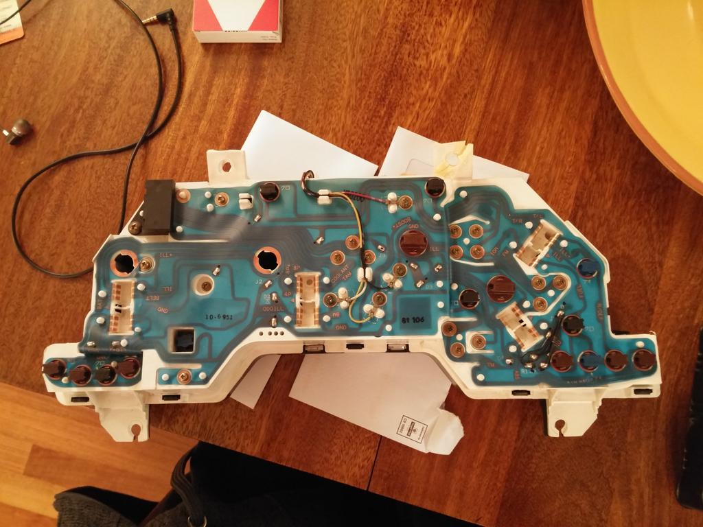
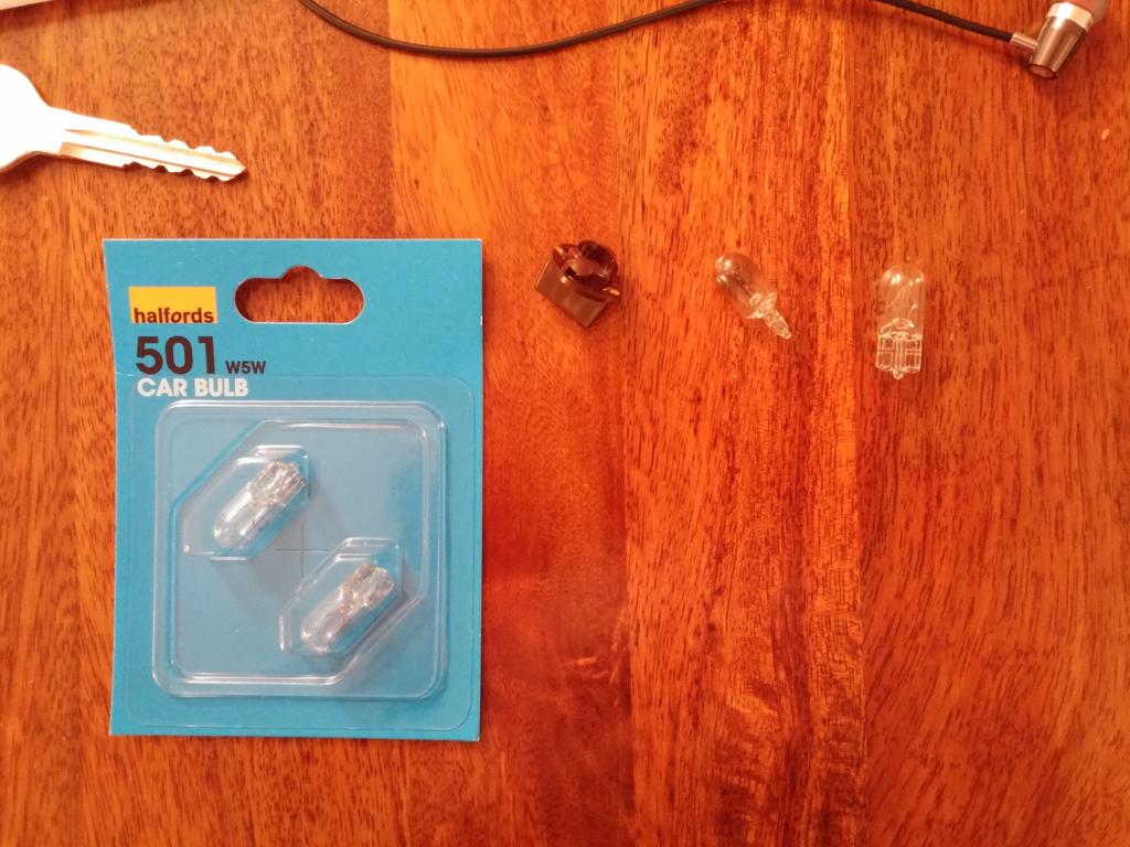
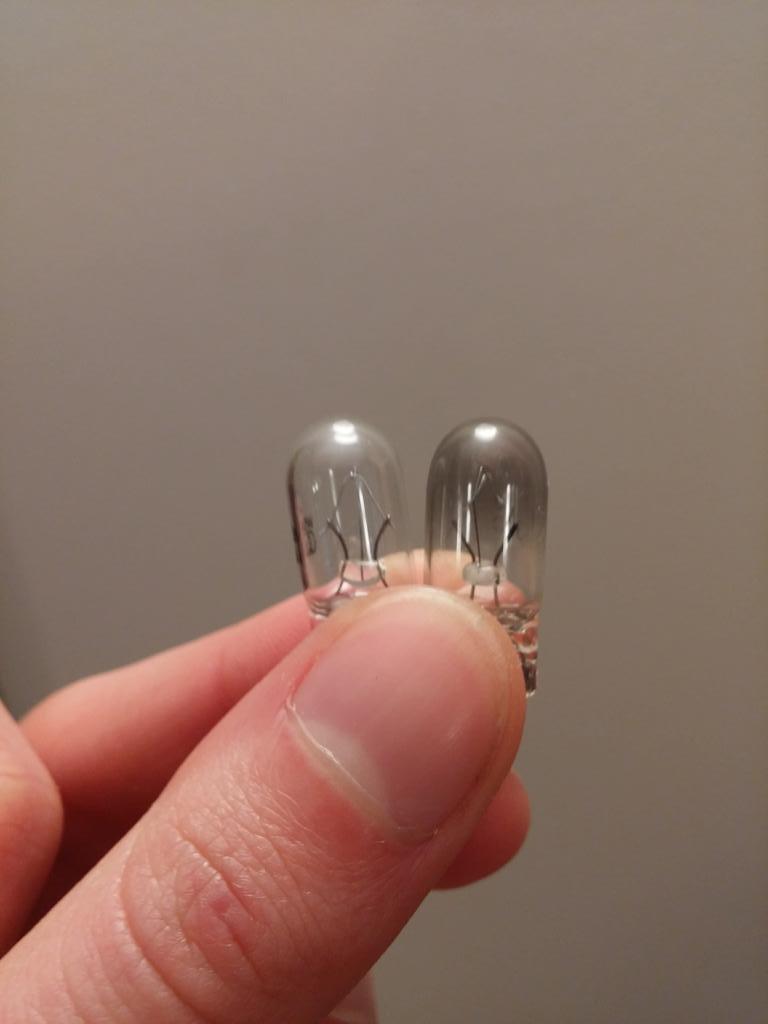
I also decided to re-calibrate my speedo yet again as the last time I did it, the gauge ended up reading too slow. I've done this probably 5-6 times now and the reason I keep re-doing it is I am trying to get it back to where the miles calculate correctly as you are driving. If the speedo is calibrated to be dead on with the GPS the miles don't accumulate fast enough (they are very close but not quite right). Thus, I'm trying to get it back to where the speedo reads 5-10 mph quicker than the GPS as that was when the mileage was calculating correctly.
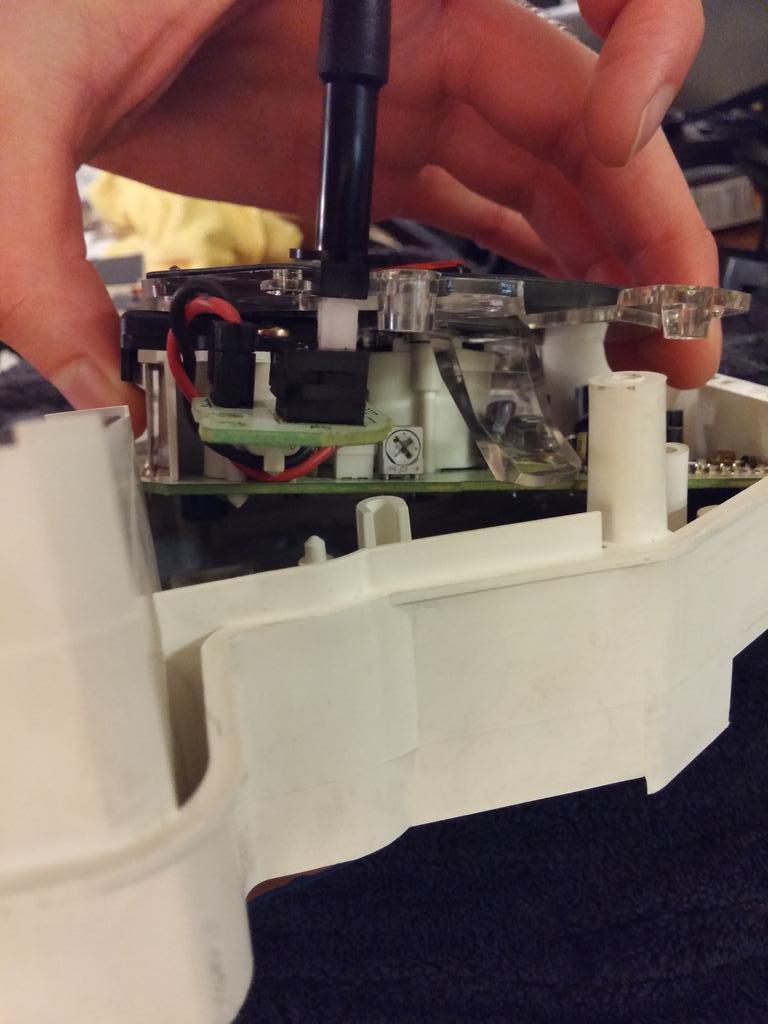
Here is how you adjust your speedo:
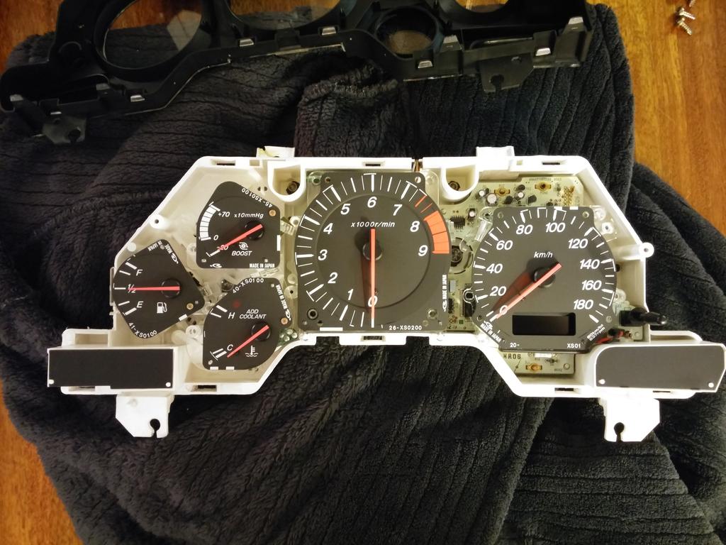
1. Remove four screws on the back.
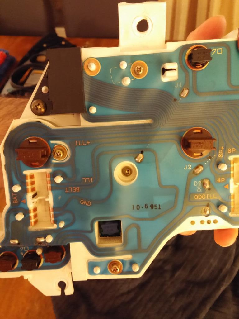
2. Remove one screw on the front where trip reset button is.
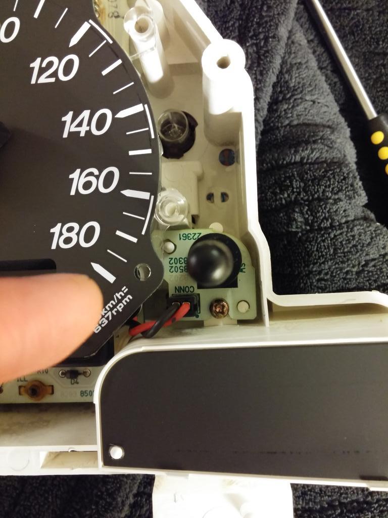
3. Lift gauge and adjust screw. Clockwise slows it down and counter-clockwise speeds it up.
**Be careful as it is VERY sensitive**.
Like 1/16 of a turn makes a large change in speed.
Today I replaced a tail light bulb, polished and waxed the car and I also replaced the large bulbs in the gauge cluster (they didn't have the right type of smaller bulbs. The old bulbs were still working but the lighting was too dim at night and judging by the difference between the old and new bulbs as shown below, I think the gauges will be brighter from now on and they might more closely match the illumination of my Defi gauges.
I also decided to re-calibrate my speedo yet again as the last time I did it, the gauge ended up reading too slow. I've done this probably 5-6 times now and the reason I keep re-doing it is I am trying to get it back to where the miles calculate correctly as you are driving. If the speedo is calibrated to be dead on with the GPS the miles don't accumulate fast enough (they are very close but not quite right). Thus, I'm trying to get it back to where the speedo reads 5-10 mph quicker than the GPS as that was when the mileage was calculating correctly.
Here is how you adjust your speedo:
1. Remove four screws on the back.
2. Remove one screw on the front where trip reset button is.
3. Lift gauge and adjust screw. Clockwise slows it down and counter-clockwise speeds it up.
**Be careful as it is VERY sensitive**.
Like 1/16 of a turn makes a large change in speed.
- Joined
- Jan 12, 2018
- Messages
- 1,415
February 2016
I purchased a GoPro Hero 4 Silver and a Ram Mount Tough Claw system:
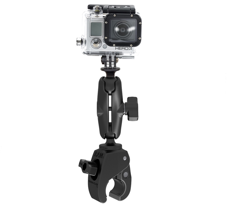
The build quality of the mount is extremely high and sturdy (albeit a bit small), but it mounts perfectly to the rear strut bar plastic although the GoPro itself is a bit farther back in the car than I would like it to be so I plan on buying a 6" extension bar from ram mount to bring the GoPro closer to the back of the front seats. I can still use the "Narrow" setting in the GoPro to get the right shot but then the picture quality is a bit softer and fuzzier than I ideally want.
The one issue I have now is audio quality as I did a test drive with the GoPro mounted and you couldn't hear my voice at all. In fact, most of the noise was just a hollow hum from the car and the occasional suspension or tire noise despite the fact that I have a full interior and to my wife and myself the car seemed relatively quiet when cruising around.
So, I need a mic and I've found a few options but now I want to know where the best place to mount it is. Mounting in the engine bay seems to be the best solution for clear sound quality as sometimes mounting on the bumper near the exhaust is subject to a lot of wind noise (surprisingly). However, I wonder if any of the mics can actually withstand the heat of the engine bay and if the induction noise on the RX-7 actually sounds any good? It certainly sounded like a vacuum cleaner on my RX-8 so the exhaust was the best option.
Once I sort out the mic issue I'm going to get a 10HZ GPS receiver as the GPS on my smartphone just doesn't cut it, and I may even get a second cheaper camera like the GoPro Hero 4 Session to mount on top of the steering column to face the gauges (for RPM and speed mostly) so that I can sync the two videos later.
I purchased a GoPro Hero 4 Silver and a Ram Mount Tough Claw system:
The build quality of the mount is extremely high and sturdy (albeit a bit small), but it mounts perfectly to the rear strut bar plastic although the GoPro itself is a bit farther back in the car than I would like it to be so I plan on buying a 6" extension bar from ram mount to bring the GoPro closer to the back of the front seats. I can still use the "Narrow" setting in the GoPro to get the right shot but then the picture quality is a bit softer and fuzzier than I ideally want.
The one issue I have now is audio quality as I did a test drive with the GoPro mounted and you couldn't hear my voice at all. In fact, most of the noise was just a hollow hum from the car and the occasional suspension or tire noise despite the fact that I have a full interior and to my wife and myself the car seemed relatively quiet when cruising around.
So, I need a mic and I've found a few options but now I want to know where the best place to mount it is. Mounting in the engine bay seems to be the best solution for clear sound quality as sometimes mounting on the bumper near the exhaust is subject to a lot of wind noise (surprisingly). However, I wonder if any of the mics can actually withstand the heat of the engine bay and if the induction noise on the RX-7 actually sounds any good? It certainly sounded like a vacuum cleaner on my RX-8 so the exhaust was the best option.
Once I sort out the mic issue I'm going to get a 10HZ GPS receiver as the GPS on my smartphone just doesn't cut it, and I may even get a second cheaper camera like the GoPro Hero 4 Session to mount on top of the steering column to face the gauges (for RPM and speed mostly) so that I can sync the two videos later.
- Joined
- Jan 12, 2018
- Messages
- 1,415
February 2016
I was just using the stock housing at the time for the test but I just bought a laundry list of items today including a skeleton housing:
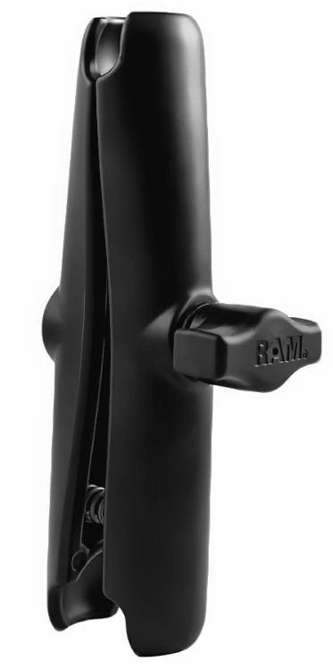
6" Ram Mount Extension so that I can bring the camera forward into the back seat area rather than sitting right above the rear strut bar.
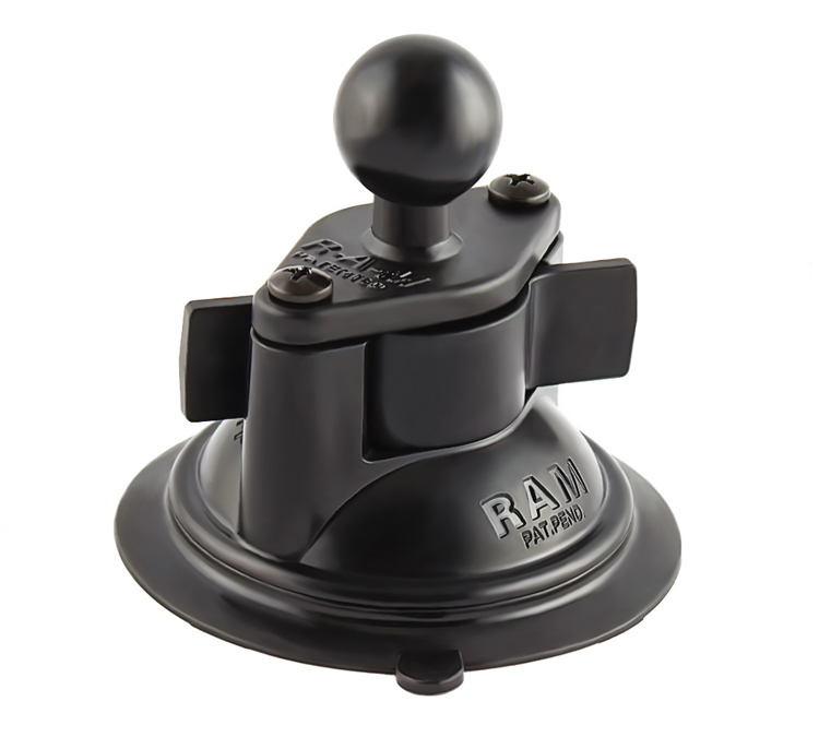
Ram Mount Suction Cup Mount in case I want to mount the Go Pro on a window sometimes;
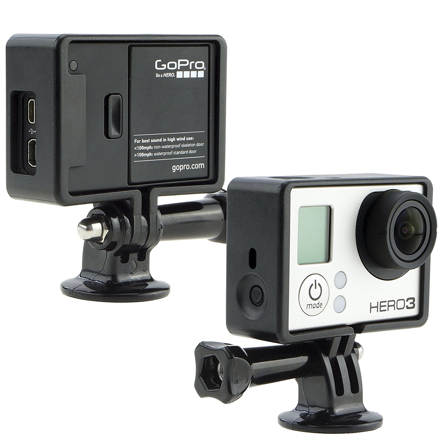
Camfix Skeleton Mount for GoPro
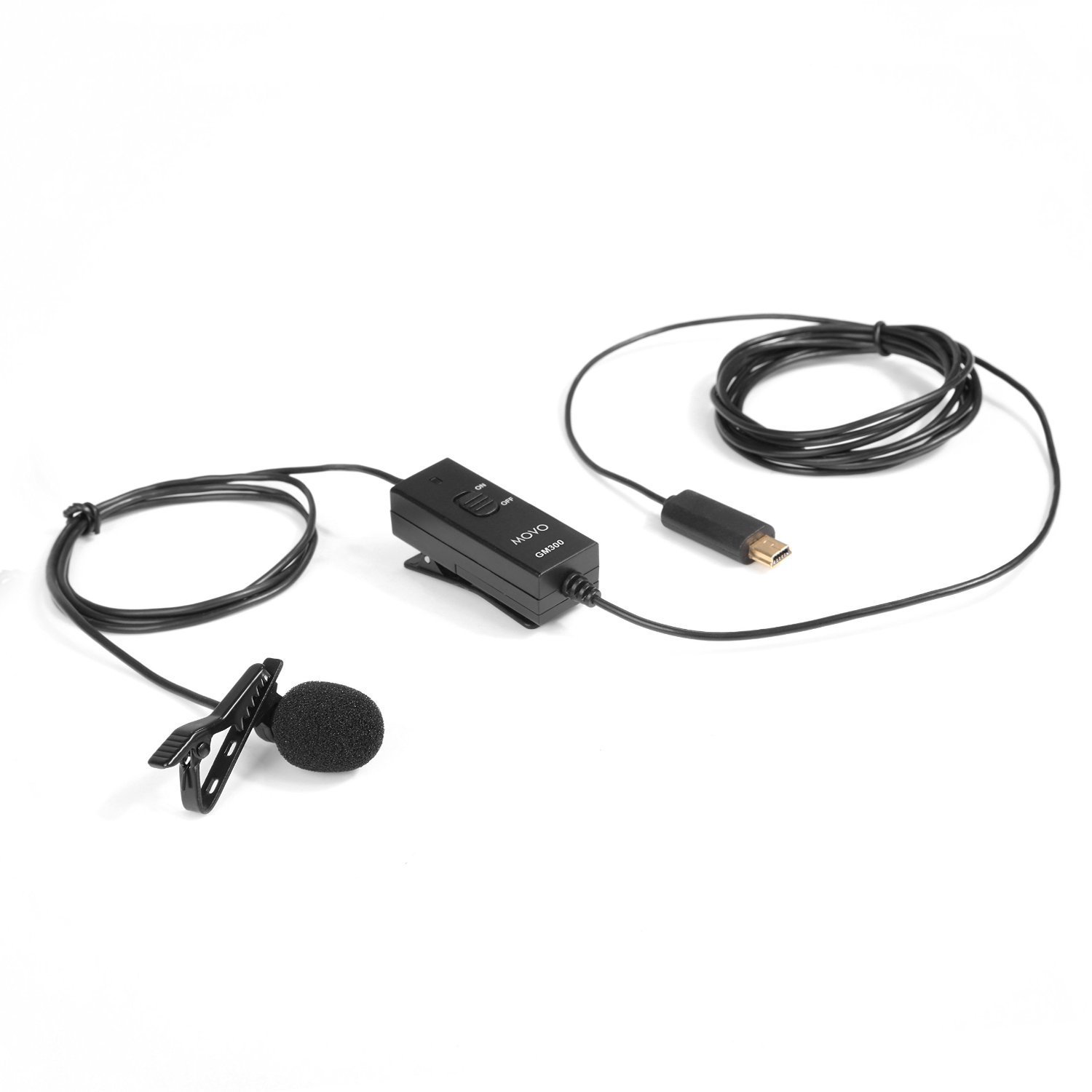
Movo GM300 Lavalier Mic which I will either mount in the engine bay on a strut tower so that it is a bit further away from the heat of the turbos, or I will attach it to the bumper near the exhaust.
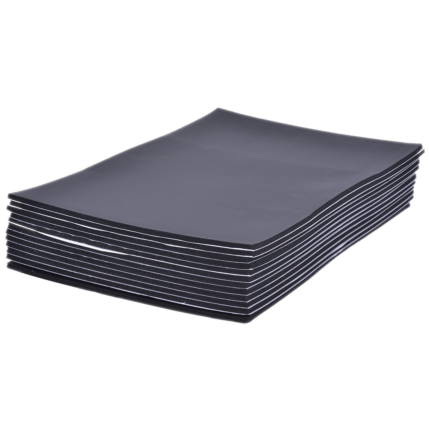
Dodo 6mm Liner (12 Sheets) to add some light soundproofing to the boot area as I currently have nothing but a spare tire and the factory carpet.
Qstarz BT-Q818XT 10HZ GPS Receiver as my phone GPS is simply unreliable and updates far too slowly for my liking.

I was just using the stock housing at the time for the test but I just bought a laundry list of items today including a skeleton housing:
6" Ram Mount Extension so that I can bring the camera forward into the back seat area rather than sitting right above the rear strut bar.
Ram Mount Suction Cup Mount in case I want to mount the Go Pro on a window sometimes;
Camfix Skeleton Mount for GoPro
Movo GM300 Lavalier Mic which I will either mount in the engine bay on a strut tower so that it is a bit further away from the heat of the turbos, or I will attach it to the bumper near the exhaust.
Dodo 6mm Liner (12 Sheets) to add some light soundproofing to the boot area as I currently have nothing but a spare tire and the factory carpet.
Qstarz BT-Q818XT 10HZ GPS Receiver as my phone GPS is simply unreliable and updates far too slowly for my liking.
- Joined
- Jan 12, 2018
- Messages
- 1,415
March 2016
A few things have arrived over the last few days.
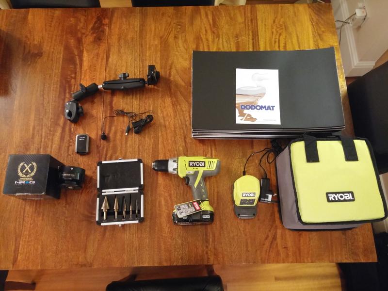
I always find that I need a drill for various things around the flat and on the car so I bought a Ryobi after a couple of recommendations (including one on here), and bought a couple of cheap step drill bits to help punch the right sized hole for my self sealing tap and self sealing leveling sensor on the front washer tank so that I can complete my water injection installation.
I plan to complete the installation and run all of the wiring into the car this weekend. I also have like 25L of distilled water ready to go.
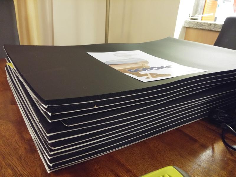
I am also going to try out some cheapo sound deadening material for the boot and spare tire area to try to quiet it down even by just a decibel or two.
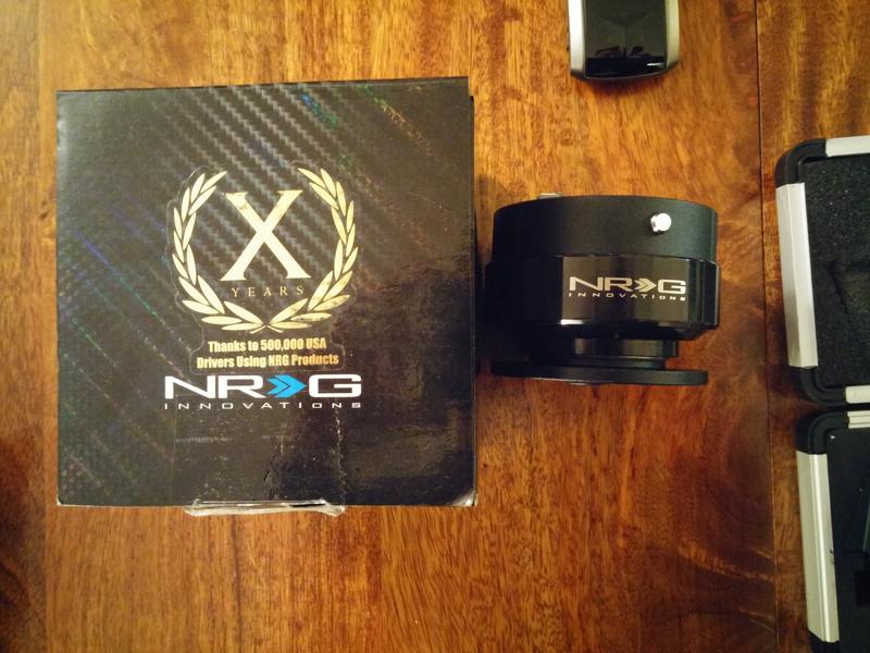
I picked up an NRG Gen 2 quick release from Essex Rotary to make getting into and out of the car easier and to also bring the steering wheel a bit closer to me as I feel like I am now too far away from the wheel after modifying my seats for extra leg room.
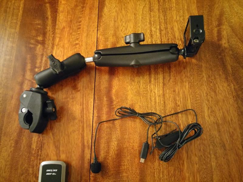
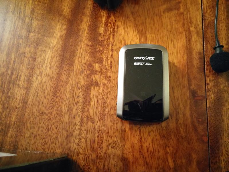
I also got a skeleton case for the GoPro, a mount extension which will clamp onto the rear strut bar as that is where I want to record track day videos from, and I picked up a lavalier mic with a foam windscreen that comes with about 9-10 feet of cabling and will allow me the flexibility of mounting on the rear bumper nearby the exhaust or in the engine bay for better sound quality.
Finally, I picked up a 10Hz GPS receiver by Qstarz which will greatly enhance tracking capability as my smartphone GPS loses itself about 50% of the time and doesn't refresh quickly enough to accurately track speed or lap times. The nice thing about the GoPro and the Qstarz is that they both connect to the TrackAddict app on Android/iOS without any issues and sync your data automatically and give you the ability to transfer effortlessly to RaceRender on the PC for eventual upload to Youtube.
A few things have arrived over the last few days.
I always find that I need a drill for various things around the flat and on the car so I bought a Ryobi after a couple of recommendations (including one on here), and bought a couple of cheap step drill bits to help punch the right sized hole for my self sealing tap and self sealing leveling sensor on the front washer tank so that I can complete my water injection installation.
I plan to complete the installation and run all of the wiring into the car this weekend. I also have like 25L of distilled water ready to go.
I am also going to try out some cheapo sound deadening material for the boot and spare tire area to try to quiet it down even by just a decibel or two.
I picked up an NRG Gen 2 quick release from Essex Rotary to make getting into and out of the car easier and to also bring the steering wheel a bit closer to me as I feel like I am now too far away from the wheel after modifying my seats for extra leg room.
I also got a skeleton case for the GoPro, a mount extension which will clamp onto the rear strut bar as that is where I want to record track day videos from, and I picked up a lavalier mic with a foam windscreen that comes with about 9-10 feet of cabling and will allow me the flexibility of mounting on the rear bumper nearby the exhaust or in the engine bay for better sound quality.
Finally, I picked up a 10Hz GPS receiver by Qstarz which will greatly enhance tracking capability as my smartphone GPS loses itself about 50% of the time and doesn't refresh quickly enough to accurately track speed or lap times. The nice thing about the GoPro and the Qstarz is that they both connect to the TrackAddict app on Android/iOS without any issues and sync your data automatically and give you the ability to transfer effortlessly to RaceRender on the PC for eventual upload to Youtube.
- Joined
- Jan 12, 2018
- Messages
- 1,415
March 2016 - Got rid of that cheap sound deadening eventually!
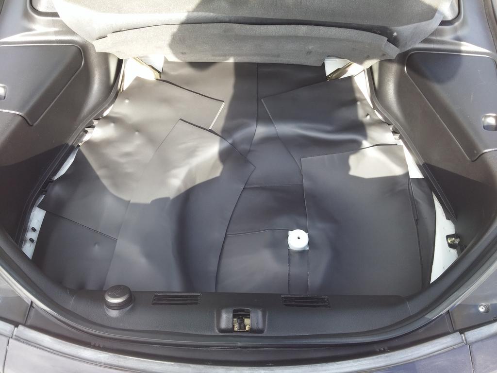
Since I couldn't finish off my water injection installation today I decided to play with the Dodomat sound deadening stuff in the boot area. I didn't really care about making it look pretty as I was more focused on covering all exposed areas (disregarding anything under the plastic trim. I took a photo before putting the spare tire back in but discovered shortly therafter that the spare tire wouldn't fit anymore! So, I had to remove quite a lot of the sound deading around the tire well just to get the tire in and now it looks pretty crap to be honest as I lost my patience and yanked a lot of the stuff out and ripped quite a bit of it. Anyway, at least the stuff comes out extremely easily leaving no residue behind since it just uses a basic adhesive similar to packing tape in feel.
I still have the rest in there that is not in the wheel well so I'll let you know if I can here anything different (doubt it).
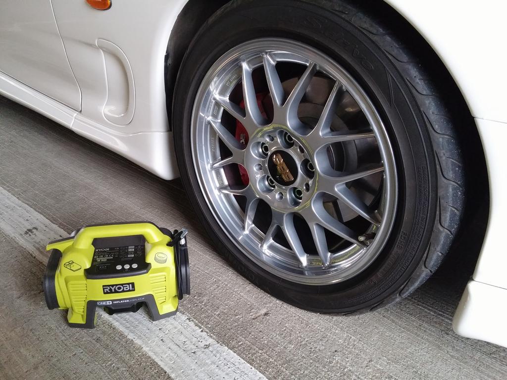
I also pumped my tires up to 32 psi on all four corners using my new Ryobi inflator. It worked very well and is quite cool because it has a LED PSI indicator and you can also set the desired pressure and it will pump up the tire until it reaches that pressure. However, on the 3rd tire the Ryobi was making some very weird noises although everything was working fine.
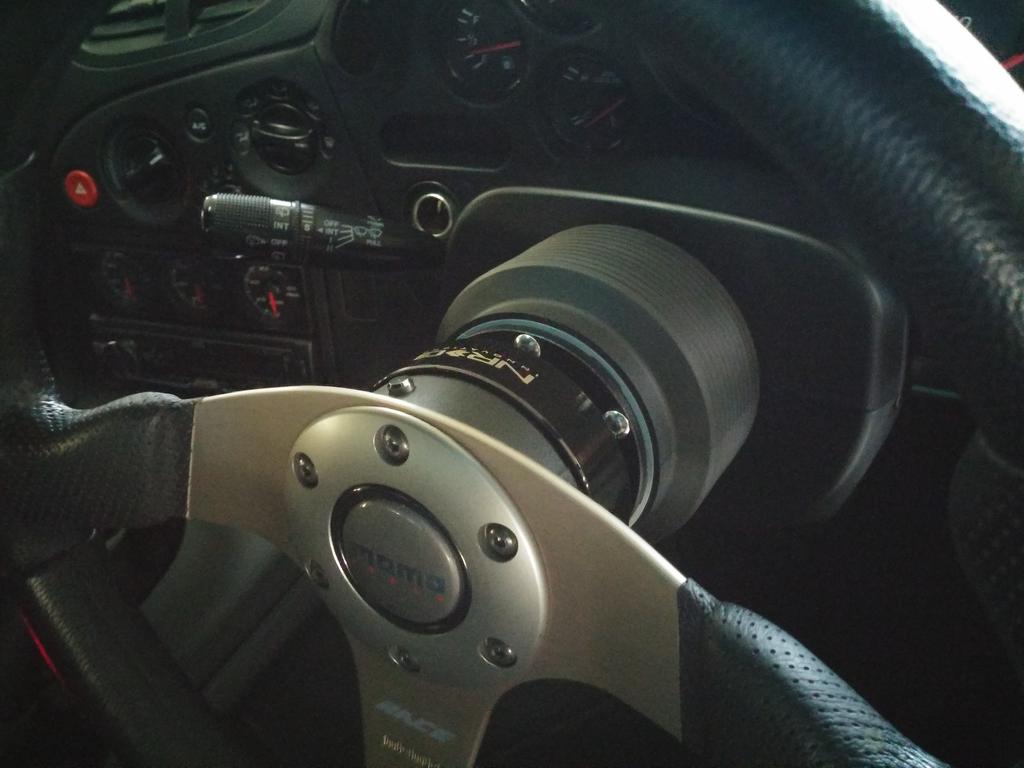
Finally, I installed my NRG Gen 2.0 quick release which was tricky only because I forgot to ground the horn wire so the horn wasn't working...Took me longer than I care to admit to figure that one out. However, the extra 2.5 inches or so is great because the steering wheel is now in my comfort range, is far away from my legs so there is absoultely no heel/toe issues, and I can see all of the gauges on the dash without ducking my head!
Since I couldn't finish off my water injection installation today I decided to play with the Dodomat sound deadening stuff in the boot area. I didn't really care about making it look pretty as I was more focused on covering all exposed areas (disregarding anything under the plastic trim. I took a photo before putting the spare tire back in but discovered shortly therafter that the spare tire wouldn't fit anymore! So, I had to remove quite a lot of the sound deading around the tire well just to get the tire in and now it looks pretty crap to be honest as I lost my patience and yanked a lot of the stuff out and ripped quite a bit of it. Anyway, at least the stuff comes out extremely easily leaving no residue behind since it just uses a basic adhesive similar to packing tape in feel.
I still have the rest in there that is not in the wheel well so I'll let you know if I can here anything different (doubt it).
I also pumped my tires up to 32 psi on all four corners using my new Ryobi inflator. It worked very well and is quite cool because it has a LED PSI indicator and you can also set the desired pressure and it will pump up the tire until it reaches that pressure. However, on the 3rd tire the Ryobi was making some very weird noises although everything was working fine.
Finally, I installed my NRG Gen 2.0 quick release which was tricky only because I forgot to ground the horn wire so the horn wasn't working...Took me longer than I care to admit to figure that one out. However, the extra 2.5 inches or so is great because the steering wheel is now in my comfort range, is far away from my legs so there is absoultely no heel/toe issues, and I can see all of the gauges on the dash without ducking my head!
- Joined
- Jan 12, 2018
- Messages
- 1,415
March 2016 - This catch can still wasn't good enough!
My oil catch can arrived today! It came extremely well packaged with a detailed booklet including how to install and clean the unit. I also really appreciate the effort Saikou Michi went to in terms of shipping and marking the item as a gift with a maximum value of $40 in order to help me avoid customs duty and VAT charges (which worked). I ordered the S3-OCC with a semi-gloss finish and red logo which I think came out pretty good. The unit is one solid piece of metal and the extra large drain valve is great. They even gave me a plastic barb fitting to screw into the drain valve and be able to hook a hose up to in order to make draining easier, although for me it will probably be easier to simply remove the catch can from the car.
I will start on the install tonight by removing the stock airbox and figuring out how to plumb the rubber hose from the filler neck to the brake master cylinder area discreetly.
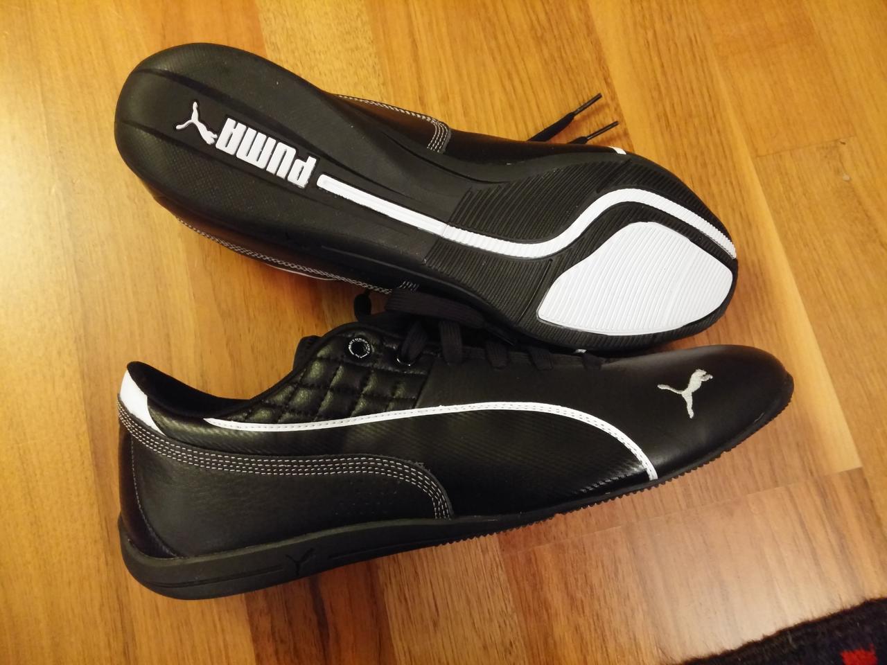
On Sunday I was looking at driving shoes and came across the Puma Drift Cat 6 shoes that were on sale on Amazon for £39.99 so I picked up a pair. They fit really nicely and are really flexible with a rounded heel. I'm looking forward to trying them on Saturday, 12th March at Donington.
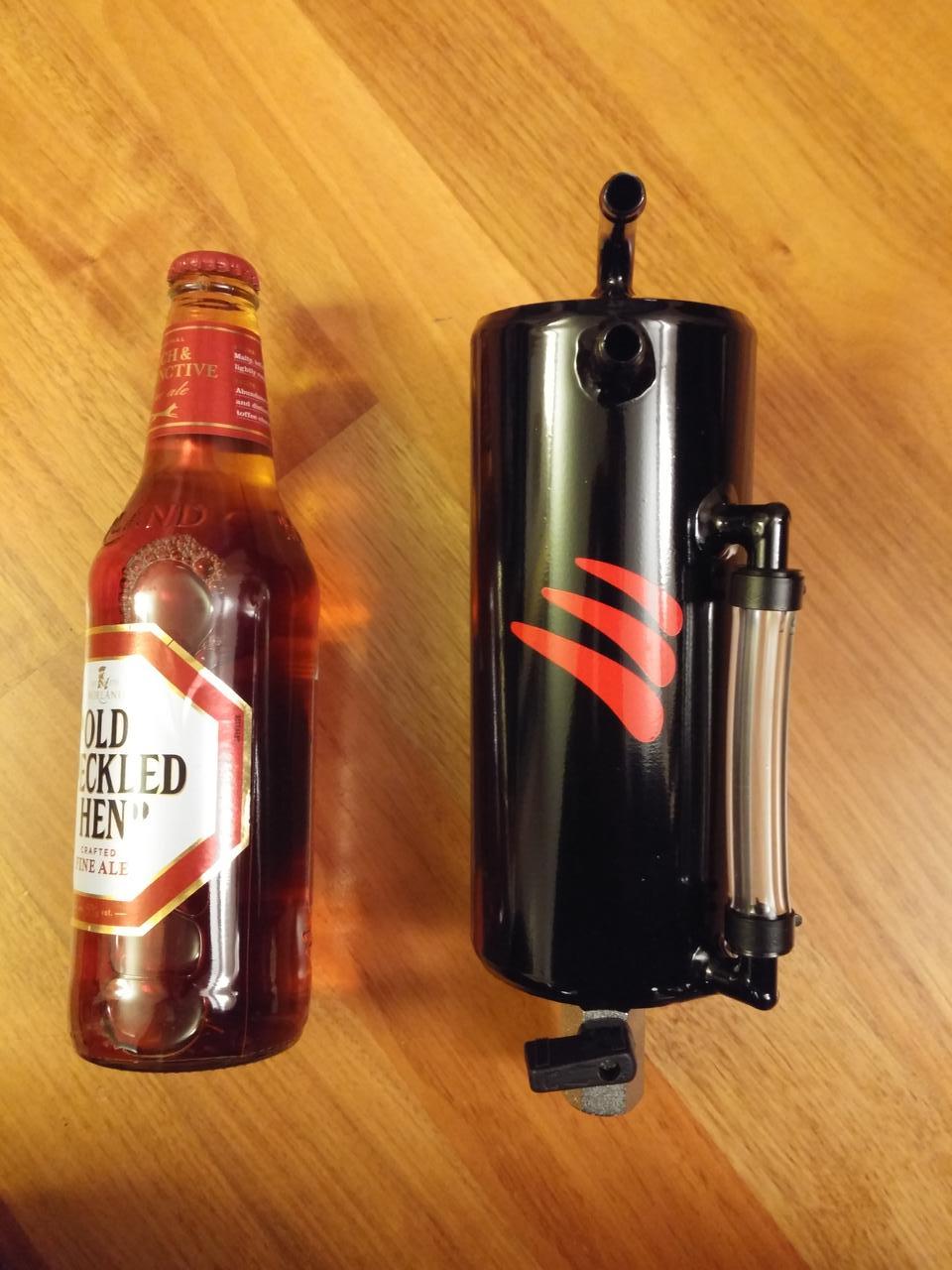
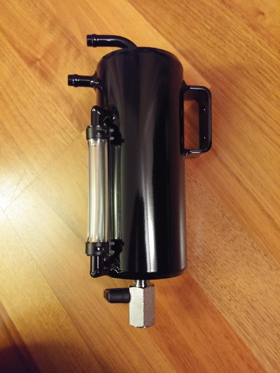
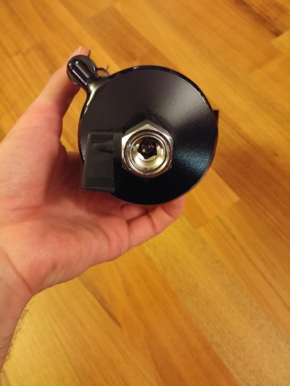
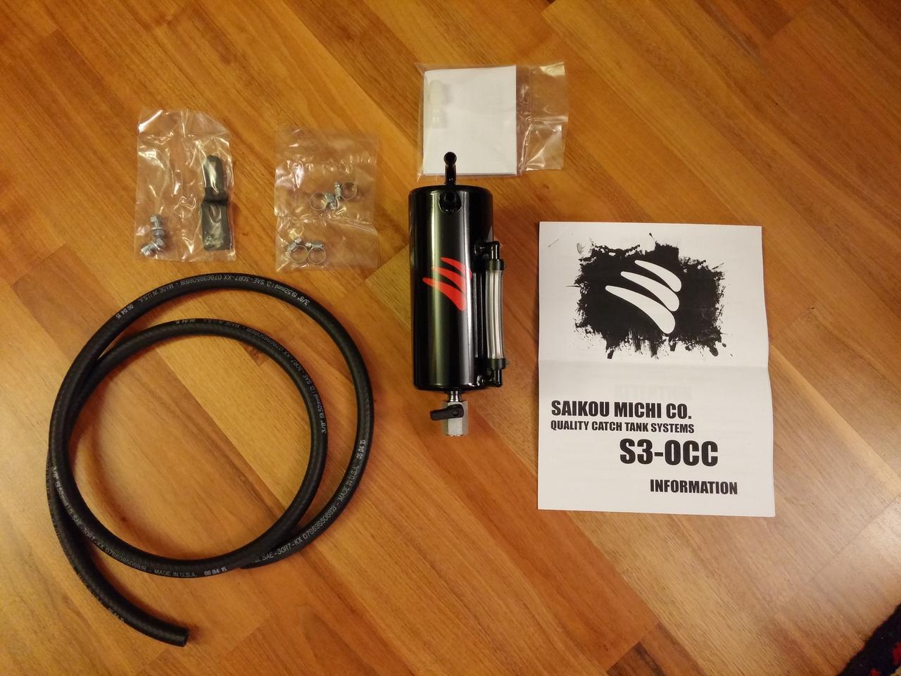
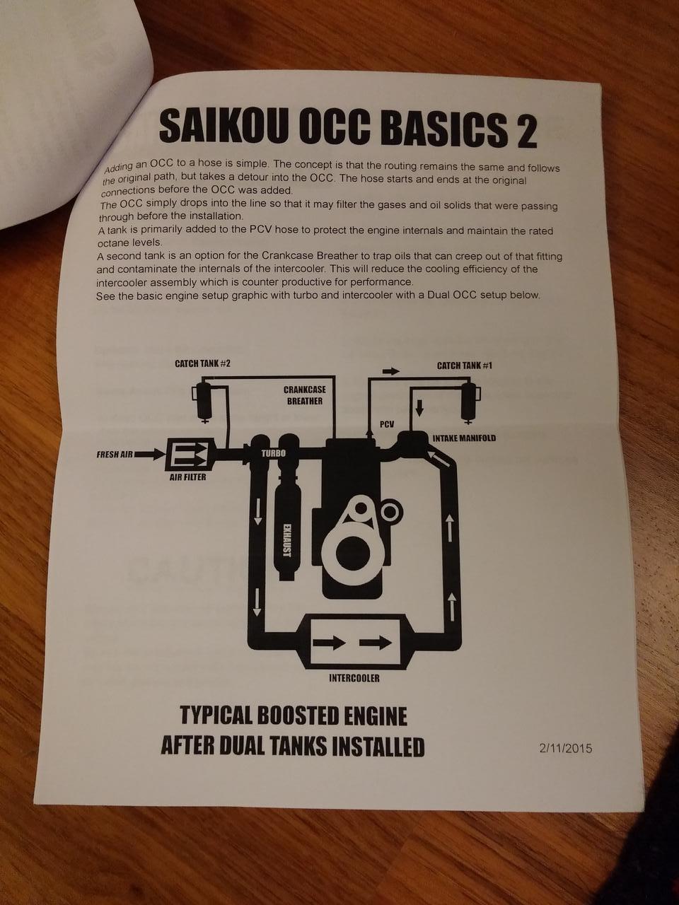
My oil catch can arrived today! It came extremely well packaged with a detailed booklet including how to install and clean the unit. I also really appreciate the effort Saikou Michi went to in terms of shipping and marking the item as a gift with a maximum value of $40 in order to help me avoid customs duty and VAT charges (which worked). I ordered the S3-OCC with a semi-gloss finish and red logo which I think came out pretty good. The unit is one solid piece of metal and the extra large drain valve is great. They even gave me a plastic barb fitting to screw into the drain valve and be able to hook a hose up to in order to make draining easier, although for me it will probably be easier to simply remove the catch can from the car.
I will start on the install tonight by removing the stock airbox and figuring out how to plumb the rubber hose from the filler neck to the brake master cylinder area discreetly.
On Sunday I was looking at driving shoes and came across the Puma Drift Cat 6 shoes that were on sale on Amazon for £39.99 so I picked up a pair. They fit really nicely and are really flexible with a rounded heel. I'm looking forward to trying them on Saturday, 12th March at Donington.
- Joined
- Jan 12, 2018
- Messages
- 1,415
March 2016
Spent some time this evening prepping the car for the catch can install and test fitting the can and running the hoses to see how much I need.
Airbox Off
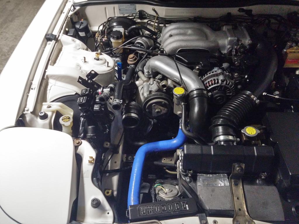
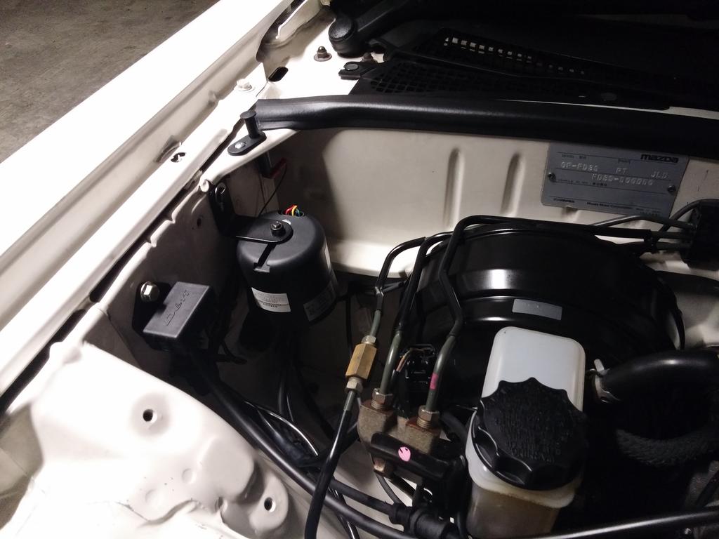
Catch Can to Go Here - Must Move Alarm Siren and Defi Boost Sensor
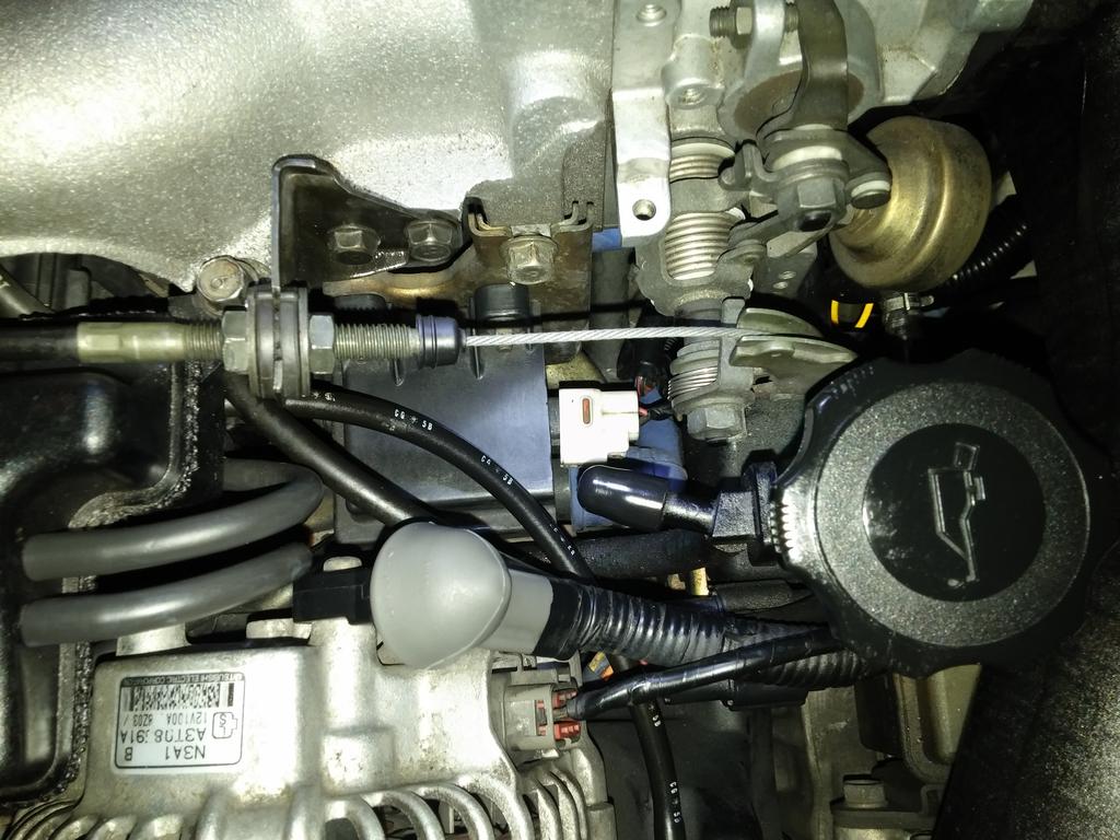
Oil Filler Neck and Hose Which Connects to Hard Line and Eventually to Primary Turbo Inlet Elbow
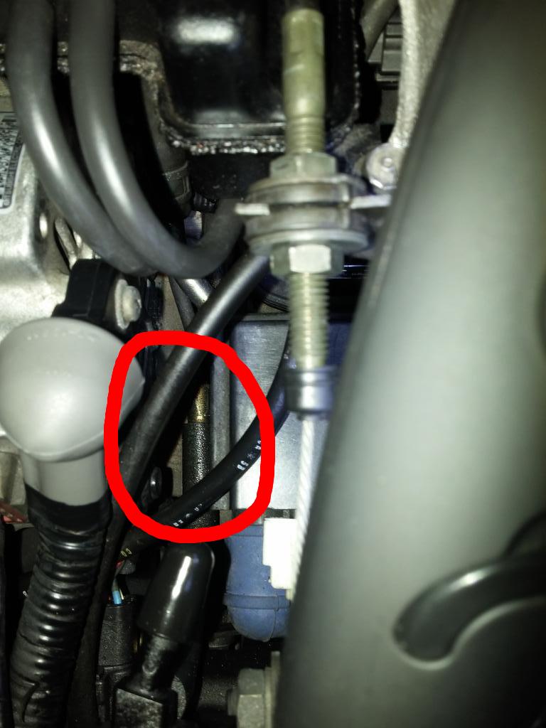
Two Hoses on Inlet Elbow - Which One is from the Filler Neck? One of Them Connects to the Oil Injectors
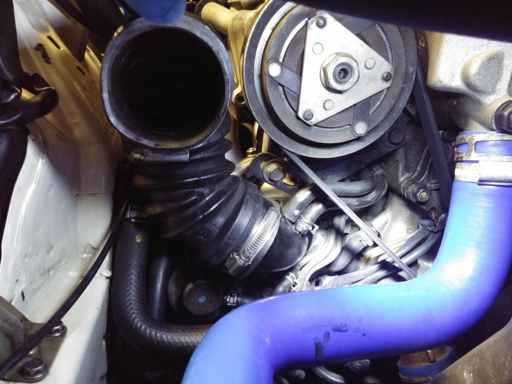
Removing Alarm Siren and Boost Gauge
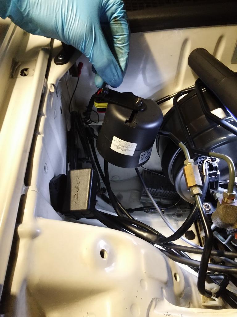
Test Fitting Catch Can - It's tight! Should have ordered angled nipples rather than standard front facing nipples
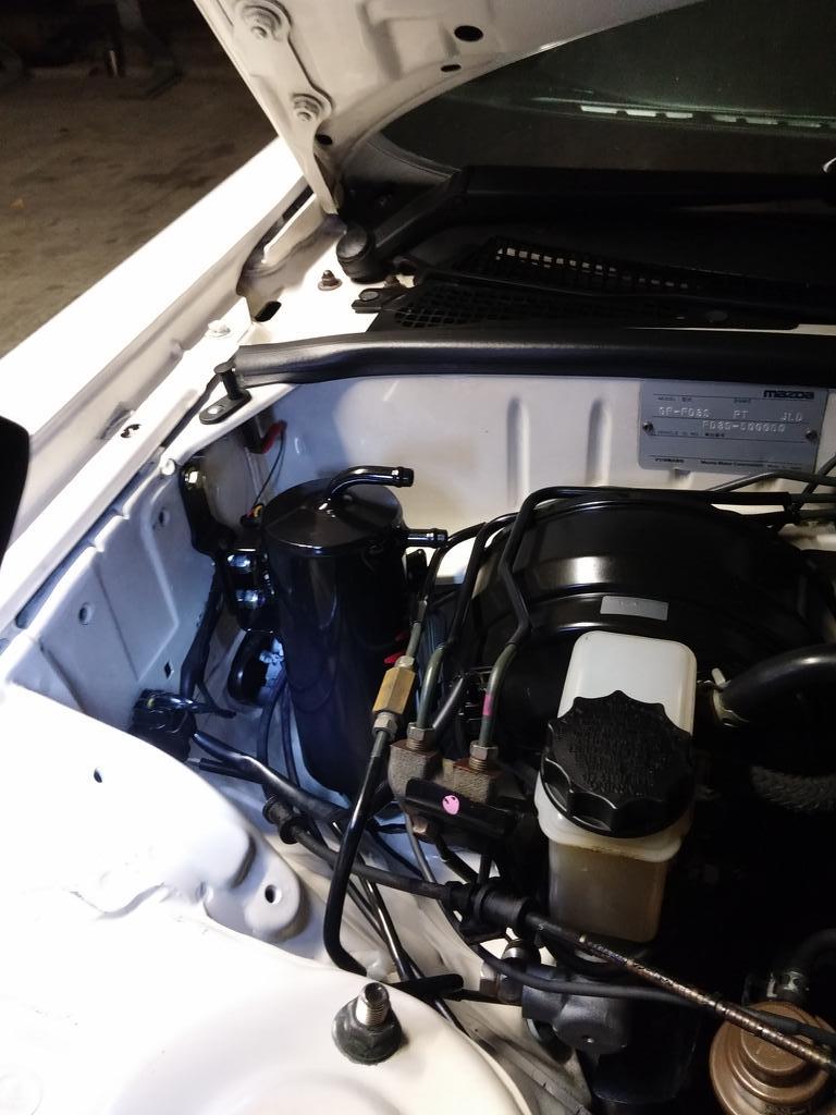
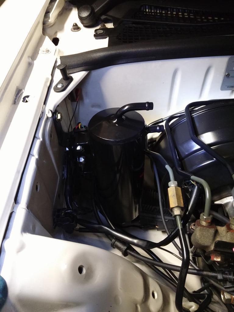
Hose Route Testing to Primary Inlet Eblow
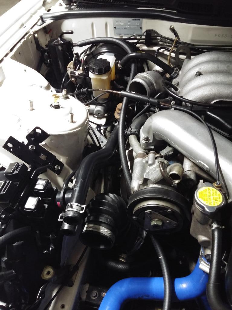
Test Fitting Catch Can, Alarm Siren and Boost Sensor Relocations (Boost Sensor Now on Shock Tower)
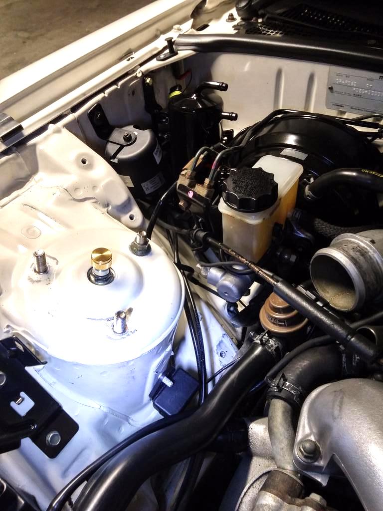
Everything is now ready to go and the hose routing is finalised. Unfortunately the alarm siren is going to have to be angled slightly but I can live with that for now.
All I need to do tomorrow is figure out how to take off the oil filler neck hose given the limited space to work with and figure out which of the primary inlet elbow hoses comes from the oil filler neck so that I can connect the hose from the catch can.
Spent some time this evening prepping the car for the catch can install and test fitting the can and running the hoses to see how much I need.
Airbox Off
Catch Can to Go Here - Must Move Alarm Siren and Defi Boost Sensor
Oil Filler Neck and Hose Which Connects to Hard Line and Eventually to Primary Turbo Inlet Elbow
Two Hoses on Inlet Elbow - Which One is from the Filler Neck? One of Them Connects to the Oil Injectors
Removing Alarm Siren and Boost Gauge
Test Fitting Catch Can - It's tight! Should have ordered angled nipples rather than standard front facing nipples
Hose Route Testing to Primary Inlet Eblow
Test Fitting Catch Can, Alarm Siren and Boost Sensor Relocations (Boost Sensor Now on Shock Tower)
Everything is now ready to go and the hose routing is finalised. Unfortunately the alarm siren is going to have to be angled slightly but I can live with that for now.
All I need to do tomorrow is figure out how to take off the oil filler neck hose given the limited space to work with and figure out which of the primary inlet elbow hoses comes from the oil filler neck so that I can connect the hose from the catch can.
- Joined
- Jan 12, 2018
- Messages
- 1,415
March 2016
Routed my catch can last night after a lot of deliberation about how I wanted to route the hoses. I tested out the following options for routing:
#1 was sort of impossible as I couldn't access the hard line near the filler neck and below the pressure chamber. In fact, I couldn't get the hose off of the hard line so it's still connected but no longer connected to the filler neck.
#2 seemed like a good idea at the time but there wasn't enough clearance for two hoses down near the inlet elbow and I was a bit concerned about oil potentially pooling up down there before it went to the catch can. The oil from the filler neck should travel upwards to the catch can rather than down towards the primary inlet elbow and back up again.
Thus, I opted for #3 and left the hard line in place and disconnected.
Plug removed from PCV nipple to lower nipple which was connected to hard line by a small rubber hose
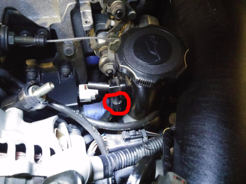
Small rubber hose that I couldn't remove from the hard line due to having no space. Now it sits as shown...Not preferred as a long-term solution because it's ugly
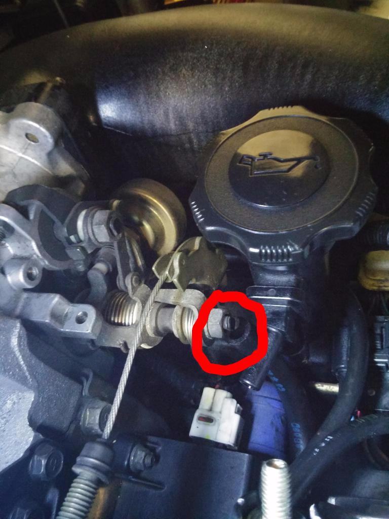
Removing primary inlet elbow hose
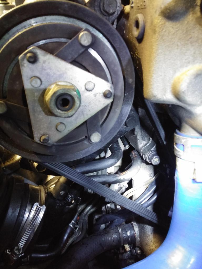
Hose from filler neck to catch can
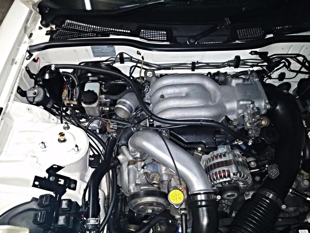
Hose connected to primary inlet elbow
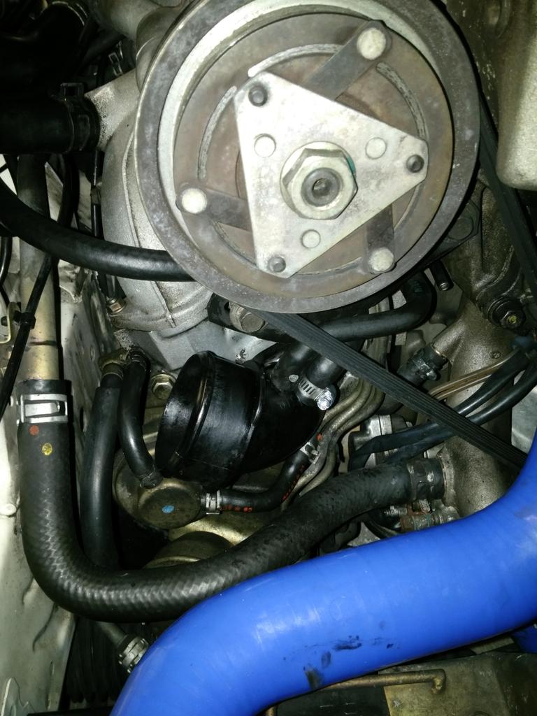
Routing of hose from catch can to inlet elbow, boost sensor relocated and alarm siren also relocated
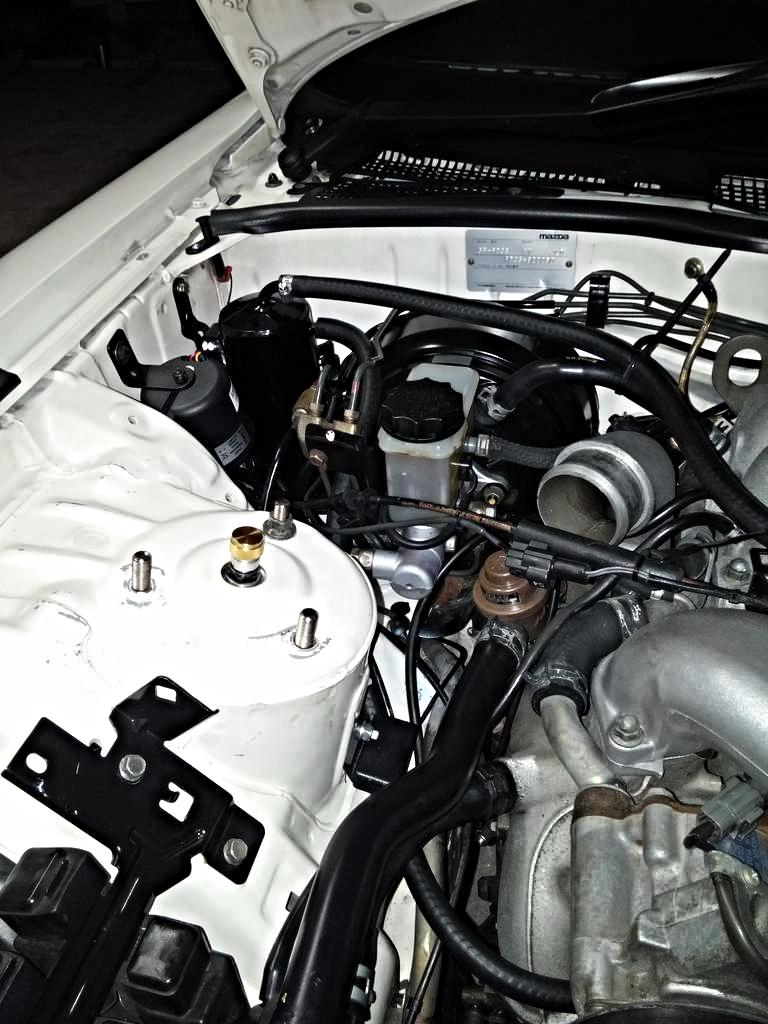
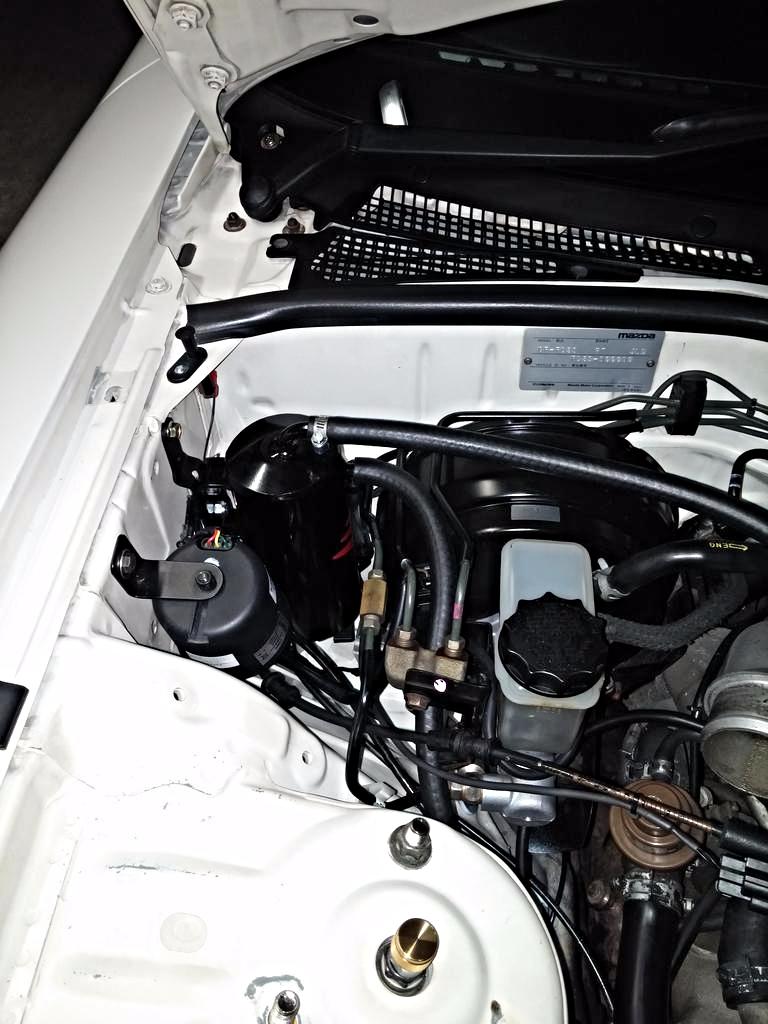
The other hose on the inlet elbow is hard as a rock so I will look to replace that at some point although it doesn't rely on vacuum to function correctly and it's not exactly going anywhere. All that's left is to clip my zip tie connections, put the airbox and hoses back on and fire it up and see if anything leaks.
The quality of the hoses is great and I'm thankful for the hose clamps because the filler neck and the inlet elbow nipples are closer to 5/16" than 3/8" (size of the rubber hose). The catch can fits very snugly because it's way larger than I ever thought it would be and the hoses are very snug on the can. This means that emptying it out will require me to remove the hoses and remove the can from the car but I guess I can live with that.
Routed my catch can last night after a lot of deliberation about how I wanted to route the hoses. I tested out the following options for routing:
- Oil filler neck to catch can to hard line near filler neck that runs down to primary turbo inlet elbow;
- Hard line near primary turbo inlet elbow to catch can to primary turbo inlet elbow;
- Oil filler neck to catch can to primary turbo inlet elbow and leaving hard line that runs from oil filler neck to primary turbo inlet elbow disconnected.
#1 was sort of impossible as I couldn't access the hard line near the filler neck and below the pressure chamber. In fact, I couldn't get the hose off of the hard line so it's still connected but no longer connected to the filler neck.
#2 seemed like a good idea at the time but there wasn't enough clearance for two hoses down near the inlet elbow and I was a bit concerned about oil potentially pooling up down there before it went to the catch can. The oil from the filler neck should travel upwards to the catch can rather than down towards the primary inlet elbow and back up again.
Thus, I opted for #3 and left the hard line in place and disconnected.
Plug removed from PCV nipple to lower nipple which was connected to hard line by a small rubber hose
Small rubber hose that I couldn't remove from the hard line due to having no space. Now it sits as shown...Not preferred as a long-term solution because it's ugly
Removing primary inlet elbow hose
Hose from filler neck to catch can
Hose connected to primary inlet elbow
Routing of hose from catch can to inlet elbow, boost sensor relocated and alarm siren also relocated
The other hose on the inlet elbow is hard as a rock so I will look to replace that at some point although it doesn't rely on vacuum to function correctly and it's not exactly going anywhere. All that's left is to clip my zip tie connections, put the airbox and hoses back on and fire it up and see if anything leaks.
The quality of the hoses is great and I'm thankful for the hose clamps because the filler neck and the inlet elbow nipples are closer to 5/16" than 3/8" (size of the rubber hose). The catch can fits very snugly because it's way larger than I ever thought it would be and the hoses are very snug on the can. This means that emptying it out will require me to remove the hoses and remove the can from the car but I guess I can live with that.
- Joined
- Jan 12, 2018
- Messages
- 1,415
March 2016
Completed my catch can install this evening and put everything back together. No leaks when I fired it up but I went for a 15 mile round trip drive stopping at Shell in between to fill up and made sure to get into boost a few times to see how everything held up. Unfortunately, when I got back I noticed that there was some oil (small amount for now) leaking from the bottom nipple on the oil filler neck!
This is the one that used to be connected to the hard line that went all the way to the primary inlet elbow, but for my catch can install I used the cap that was on the PCV nipple (now connected via the hose to the catch can) and put it on the lower vertical nipple.
I kind of expected this to happen because of gravity and that the cap might not be too tight anymore after removing it from the other nipple. So, how would you go about fixing this? Will a zip tie suffice or do I need some sort of glue on the inside of the cap and stick it back on to seal it up?
This is kind of a pressing matter because I will be going to Donington on Saturday and don't want to potentially cause a mess in my engine bay!
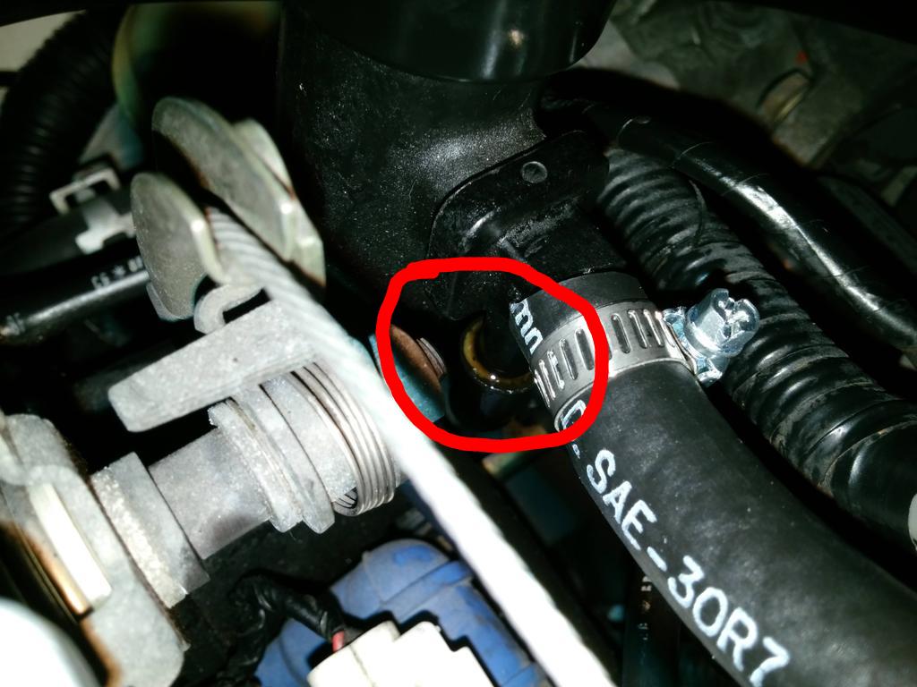
Completed my catch can install this evening and put everything back together. No leaks when I fired it up but I went for a 15 mile round trip drive stopping at Shell in between to fill up and made sure to get into boost a few times to see how everything held up. Unfortunately, when I got back I noticed that there was some oil (small amount for now) leaking from the bottom nipple on the oil filler neck!
This is the one that used to be connected to the hard line that went all the way to the primary inlet elbow, but for my catch can install I used the cap that was on the PCV nipple (now connected via the hose to the catch can) and put it on the lower vertical nipple.
I kind of expected this to happen because of gravity and that the cap might not be too tight anymore after removing it from the other nipple. So, how would you go about fixing this? Will a zip tie suffice or do I need some sort of glue on the inside of the cap and stick it back on to seal it up?
This is kind of a pressing matter because I will be going to Donington on Saturday and don't want to potentially cause a mess in my engine bay!
Online statistics
- Members online
- 4
- Guests online
- 1,375
- Total visitors
- 1,379
Totals may include hidden visitors.


